High-efficiency adjustable gear burr grinding device for machining

A mechanical processing and high-efficiency technology, applied in mechanical equipment, belts/chains/gears, gear teeth, etc., can solve the problems of high use limitations, low grinding efficiency, poor adjustment effect, etc., to ensure cleanliness, improve Grinding efficiency and ensuring smoothness

Inactive Publication Date: 2020-09-25
闫政凤
View PDF1 Cites 5 Cited by
  • Summary
  • Abstract
  • Description
  • Claims
  • Application Information

AI Technical Summary

Problems solved by technology

[0005] In order to solve the above technical problems, the present invention provides a high-efficiency adjustable gear burr grinding device for mechanical processing to solve the burr grinding effect on the tooth profile parts on both sides of the gear when the existing similar gear burr grinding devices are in use. Poor, usually requires manual grinding on both sides of the gear tooth profile, the grinding efficiency is low, it cannot meet the needs of large-scale gear processing, and the adjustment effect of the device itself is poor, and it cannot be effectively indexed according to the gear Adaptive adjustment of circle diameter specification and gear thickness can only be applied to the grinding and use of a single specification gear, resulting in high limitations in its use and affecting the effect of grinding burrs on the tooth profiles on both sides of the gear.

Method used


Image

  • High-efficiency adjustable gear burr grinding device for machining
  • High-efficiency adjustable gear burr grinding device for machining
  • High-efficiency adjustable gear burr grinding device for machining

Examples


Embodiment

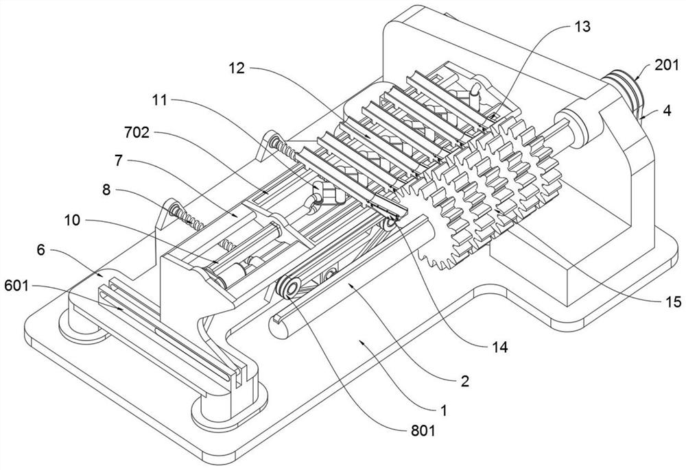
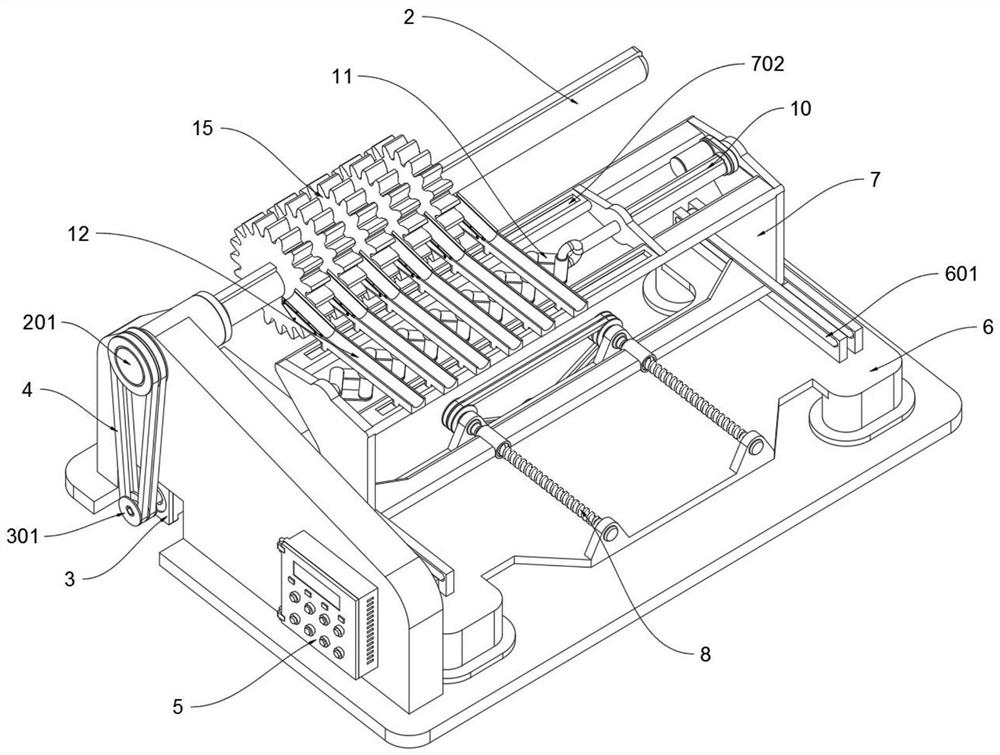
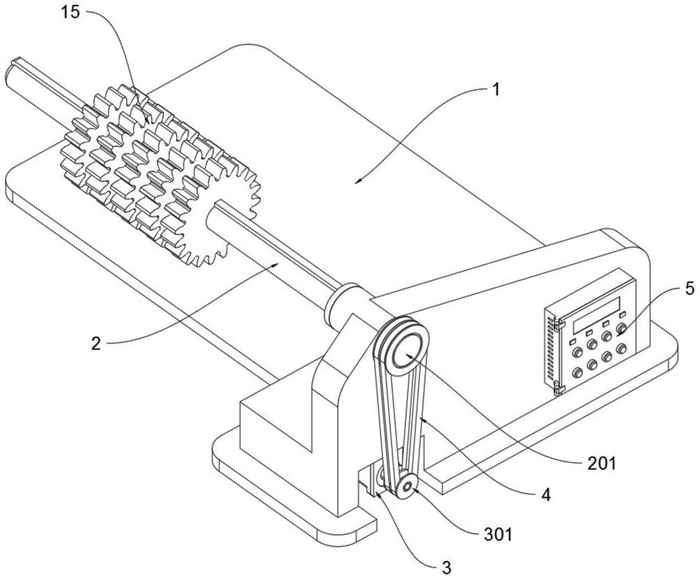
[0032] as attached figure 1 to attach Figure 8 Shown:

[0033]The invention provides a high-efficiency adjustable gear burr grinding device for mechanical processing, which includes a drive shaft 2, a drive motor 3, a tool support seat 6, a tool support frame 7, an adjustment motor 9, an electric push rod 10, a telescopic frame 11 and The cutting blade 13; the driving shaft 2 is connected to the top of the base 1, and the gear 15 is movably connected to the outside of the driving shaft 2; the driving motor 3 is electrically connected to the control electric box 5 through the power line, and the control electric box 5 is installed on the right side of the base 1 On the side outer wall, and the control electric box 5 is connected with the external power supply line; the right end of the driving shaft 2 is connected to the top of the right end of the base 1, and the right end of the driving shaft 2 is provided with a driven pulley A201, and the driving motor 3 is installed on t...


PUM


Abstract

The invention provides a high-efficiency adjustable gear burr grinding device for machining, and relates to the technical field of machining. The device solves the problems that when an existing gearburr grinding device is used, the grinding effect on burrs contained in tooth profile parts on the two sides of a gear is poor, secondary grinding operation generally needs to be conducted on the tooth profile parts on the two sides of the gear manually, the grinding efficiency is low, and the requirement for large-batch gear machining cannot be met. The high-efficiency adjustable gear burr grinding device for machining comprises a cutter supporting seat and a cutter supporting frame, a driving motor is electrically connected with a control electric box through a power line, the control electric box is installed on the outer wall of the right side of a base, the control electric box is connected with an external power supply circuit, and the cutter supporting seat is located at the top ofthe base. According to the high-efficiency adjustable gear burr grinding device for machining, a cutting blade at the front end of a U-shaped cutter is used for cutting and removing burrs left on thetooth profile part of the outer side of the gear, and after the burrs are cut and removed, the tooth profile part of the outer side of the gear is ground through grinding blocks, so that the smoothness of the tooth profile parts of the two sides of the gear is guaranteed.

Description

technical field [0001] The invention belongs to the technical field of mechanical processing, and more specifically relates to a high-efficiency adjustable gear burr grinding device for mechanical processing. Background technique [0002] A gear is a mechanical element with teeth on the rim that can continuously mesh to transmit motion and power. The application of gears in transmission has appeared very early. It appears that with the development of production, the stability of gear operation has been paid attention to, and the gear needs to be polished after production. [0003] The gear burr grinding device can refer to the CN106826450B patent, which mainly includes air outlet holes on the second rotating shaft in the working cylinder, the hollow grinding wheel fixedly installed on the second rotating shaft is provided with frosted fan blades, and the outer bag of the air bag is installed on the frosted fan blades. Coated with fine sandpaper, a one-way air intake hole is...

Claims


Application Information

Patent Timeline
Patent Type & Authority Applications(China)
IPC IPC(8): B23F19/00B23F19/02
CPCB23F19/00B23F19/02
Inventor 闫政凤
Owner 闫政凤
Why Eureka
Try Eureka