Efficient two-for-one twisting stranding machine

A plying machine and ply twisting machine technology, which is applied to spinning machines, continuous winding spinning machines, textiles and papermaking, etc. It can solve the problems of insufficient sealing of gear reduction boxes, poor production cycle capability, and high production costs, etc. To solve the problem, to achieve the effect of stable rigidity, not easy to get stuck, and improve twisting efficiency

Active Publication Date: 2020-09-25
宁波市祥宇机械有限公司
View PDF8 Cites 0 Cited by
  • Summary
  • Abstract
  • Description
  • Claims
  • Application Information

AI Technical Summary

Problems solved by technology

[0003] The twist length control method of the previous steel wire stranding machine is to use the ratio of the driving wheel and the driven wheel of the mechanical reduction box to adjust the gear reduction ratio and change the speed of the traction wheel, so as to control the twist length of the steel wire strand. The mechanical gear box is used to adapt to the production cycle, because different specifications of steel wire strands have different lay lengths, so every time the machine tool changes a specification of steel wire, technicians are required to match the ratio between the driving wheel and the driven wheel. The gear reduction ratio is not only troublesome to replace, but also needs to reserve the ratio of active and driven gears corresponding to various specifications of steel wires, and the production cost is high.
Another important defect is that the gear reducer needs to be maintained regularly, and the oil in the reducer needs to be replaced. If the sealing of the gear reducer is not in place, there will be oil leakage

Method used


Image

  • Efficient two-for-one twisting stranding machine
  • Efficient two-for-one twisting stranding machine
  • Efficient two-for-one twisting stranding machine

Examples


Embodiment Construction

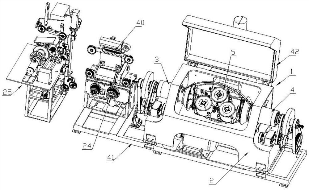
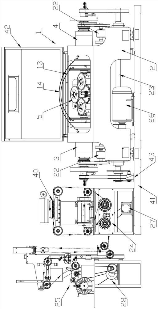
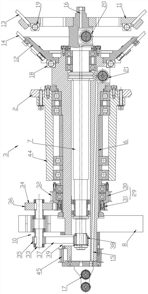
[0036] refer to Figure 1 to Figure 9 , the present invention provides a kind of high-efficiency two-for-one twisting and plying machine, comprising plying machine 1, plying machine 1 comprises fuselage support 2 and left spindle device 3 and right spindle device 4 that are symmetrically installed on fuselage support 2, left spindle device 3 The same structure as the right spindle device 4; a cradle device 5 is installed between the left spindle device 3 and the right spindle device 4; the left spindle device 3 includes a hollow outer spindle 6, an inner spindle 7 and a rotating bearing fixed on the outer spindle 6 The seat 8 and the inner core shaft 7 are rotatably fitted in the outer main shaft 6, which can greatly shorten the size in the axial direction compared with the side-by-side arrangement, thereby reducing the overall size of the entire device and simplifying the mechanism; the outer main shaft of this embodiment 6 is rotatably installed with a central reversing asse...


PUM


Abstract

The invention provides an efficient two-for-one twisting stranding machine. The efficient two-for-one twisting stranding machine comprises a stranding machine body, wherein the stranding machine bodycomprises a machine body support, a left main shaft device and a right main shaft device; the left main shaft device and the right main shaft device are symmetrically installed on the machine body support; the left main shaft device comprises a hollow outer main shaft, an inner mandrel and a rotary bearing seat fixed to the outer main shaft; the inner mandrel is rotatably sleeved with the outer main shaft; a central reversing assembly is rotatably installed on the outer main shaft, and a variable-speed transmission mechanism is eccentrically installed on the rotary bearing seat and is connected with the inner mandrel and the central reversing assembly; the inner mandrel is sleeved with the outer main shaft, the whole structure is compact, and meanwhile the whole rigidity of the inner mandrel and the outer main shaft is more stable. Power reversing is achieved through the rotary bearing seat, the central reversing assembly, the variable-speed transmission mechanism and a reversing gearbox; and stepless control can be conducted on traction speed through a servo motor and an encoder, the purpose of random lay length control can be achieved, the whole production efficiency is high, and the universality is good.

Description

technical field [0001] The invention relates to the technical field of twisting machines, in particular to a high-efficiency two-for-one twisting machine. Background technique [0002] Steel wire twisting products are produced by rotating multiple monofilaments through twisting equipment. Generally, single-twisting machines and double-twisting machines are used for production, so the production efficiency of steel wire twisting is limited. [0003] The twist length control method of the previous steel wire stranding machine is to use the ratio of the driving wheel and the driven wheel of the mechanical reduction box to adjust the gear reduction ratio and change the speed of the traction wheel, so as to control the twist length of the steel wire strand. The mechanical reduction box is used to adapt to the production cycle, because different specifications of steel wire strands have different lay lengths, so every time the machine tool changes a specification of steel wire, it...

Claims


Application Information

Patent Timeline
Patent Type & Authority Applications(China)
IPC IPC(8): D01H7/86D01H1/241D01H5/32
CPCD01H7/86D01H1/241D01H5/32
Inventor 李炜赵亮亮应琛波俞建军沈雷
Owner 宁波市祥宇机械有限公司
Why Eureka
Try Eureka