An ultrasonic cleaning device for refrigerant pipes in an air-conditioning water system

A technology for cleaning devices and refrigerant pipes, which is applied in the direction of cleaning heat transfer devices, vibration cleaning, lighting and heating equipment, etc. It can solve the problems that energy cannot be effectively delivered, affects the heat exchange effect of coils, and takes a long time for maintenance and replacement. , to achieve the effect of fast and convenient disassembly and cleaning, low maintenance and cleaning costs, and low labor costs

Active Publication Date: 2021-11-05
中筑科技股份有限公司
View PDF6 Cites 0 Cited by
  • Summary
  • Abstract
  • Description
  • Claims
  • Application Information

AI Technical Summary

Problems solved by technology

[0003] After a period of operation of the air-conditioning water system, the inner walls of the refrigerant pipes, solenoid valves or capillary tubes installed on the fan coil unit will be oxidized and covered by sediment accumulation. The most important thing is that it will also affect the heat exchange effect of the coil, resulting in that the energy cannot be effectively transported, and there are defects of no energy saving and poor effect. In the prior art, it is difficult to take corresponding measures to eliminate the above-mentioned faults when encountering the above-mentioned situation , generally only the pipelines and solenoid valves on both sides can be replaced, and since the fan coils are generally installed in the ceiling of the room, the refrigerant pipeline is at a higher position, which will increase the maintenance cost and require maintenance and replacement. The time is also longer, which greatly affects the use of air conditioners
Ultrasonic cleaning technology has been widely used, but how to apply it to the cleaning of air-conditioning refrigerant pipes has not been reported

Method used


Image

  • An ultrasonic cleaning device for refrigerant pipes in an air-conditioning water system
  • An ultrasonic cleaning device for refrigerant pipes in an air-conditioning water system
  • An ultrasonic cleaning device for refrigerant pipes in an air-conditioning water system

Examples


Embodiment Construction

[0041] In order to make the purpose, technical solutions and advantages of the embodiments of the present invention more clear, the technical solutions in the embodiments of the present invention will be clearly and completely described below in conjunction with the drawings in the embodiments of the present invention.

[0042] In the description of the present invention, it should be noted that unless otherwise specified, the meaning of "plurality" is two or more; the terms "upper", "lower", "left", "right", "inner ", "outside", "front end", "rear end", "top", "bottom" and other indicated orientations or positional relationships are based on the orientations or positional relationships shown in the drawings, and are only for the convenience of describing the present invention and simplifying the Describes, but does not indicate or imply that the device or element referred to must have a specific orientation, be constructed in a specific orientation, and operate in a specific o...


PUM


Abstract

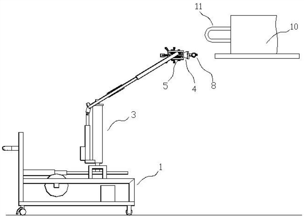
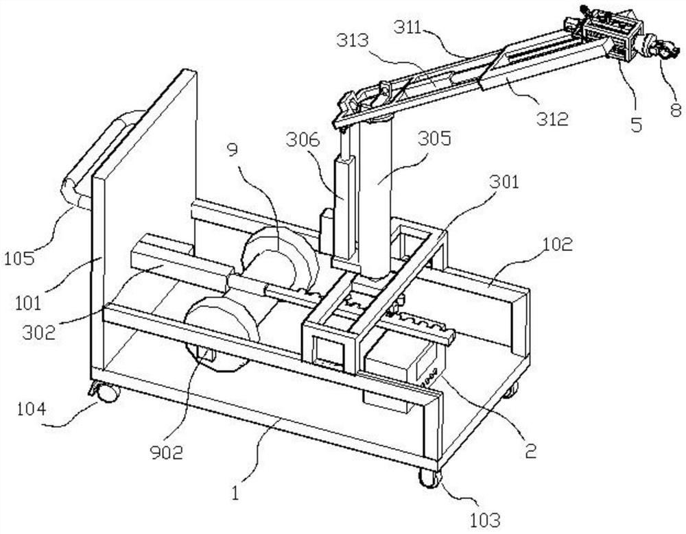
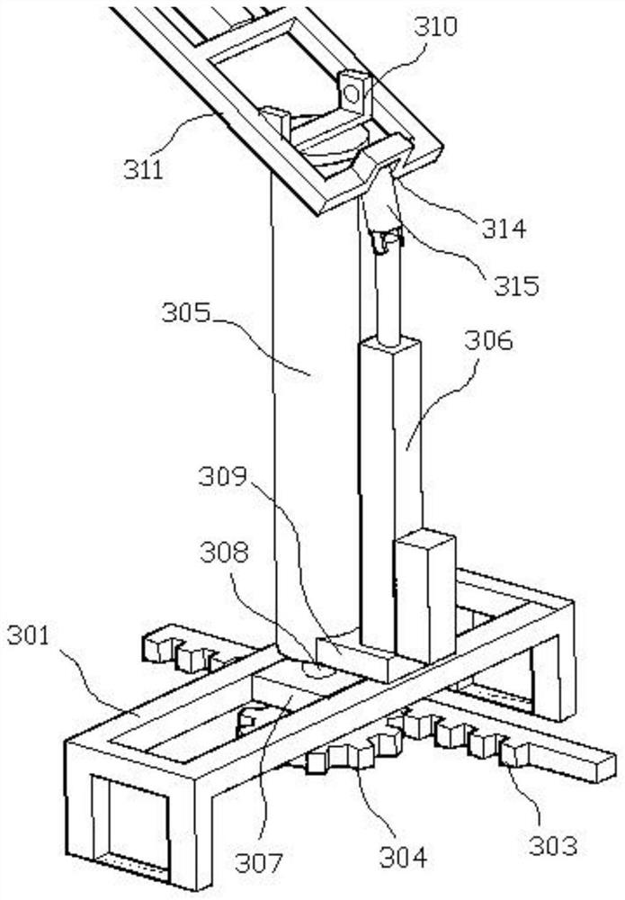
The invention discloses an ultrasonic cleaning device for refrigerant pipes of an air-conditioning water system, relates to the technical field of air-conditioning system cleaning, and comprises an ultrasonic generator, a transducer, a cart, and a pushing mechanism. The transducer is arranged on the pushing mechanism. There is a pipeline clamp on the top, and the cart is used for moving, which includes a rear vertical plate and side brackets; a pushing mechanism is used to push the transducer to the vicinity of the refrigerant pipe; the transducer is movably set on the On the pushing mechanism, the transducer includes a cylindrical conversion section and a conical output section; a pipe clamp, used for clamping the refrigerant pipe, is detachably connected to the output section of the transducer. The ultrasonic cleaning device for refrigerant pipes of the present invention has the advantages of low maintenance and cleaning cost, fast and convenient cleaning and disassembly, good cleaning effect, high consistency, high efficiency, low labor cost, and environmental friendliness.

Description

technical field [0001] The invention relates to the technical field of air conditioner cleaning, in particular to an ultrasonic cleaning device for refrigerant pipes of an air conditioner water system. Background technique [0002] The fan coil unit can be divided into a water circuit and an air circuit. The water is supplied with cold (hot) medium water by the cold (hot) source equipment (such as a refrigerator) of the central air conditioner, and is transported to the coil pipe for circulation under the action of the water pump. The water system Including refrigerant pipes, fan coils, solenoid valves or capillary tubes, etc. The air path is that the air is sucked into the room by the fan through the air return port, then crosses the coil, exchanges heat with the cold (hot) medium water in the coil, cools down and dehumidifies, and then is sent into the room by the air supply port. This cycle is repeated so that the indoor temperature and humidity can be adjusted. [0003...

Claims


Application Information

Patent Timeline
Patent Type & Authority Patents(China)
IPC IPC(8): F28G7/00F28G15/02
CPCF28G7/00F28G15/02
Inventor 张子谦张子豪孙哲政施其虎刘怀华王家燕武瑞丽
Owner 中筑科技股份有限公司
Why Eureka
Try Eureka