Dragging type optical cable laying plough for laying optical cables in shallow soil layer

A drag-type, optical cable technology, applied in optical fiber/cable installation, optics, light guide, etc., can solve problems such as inability to automate construction and laying, and achieve the effect of eliminating manual burial links, strong compatibility, and labor cost savings

Inactive Publication Date: 2020-09-25
武汉长恒如工艺品有限公司
View PDF0 Cites 5 Cited by
  • Summary
  • Abstract
  • Description
  • Claims
  • Application Information

AI Technical Summary

Problems solved by technology

[0002] With the development of the economy, people have higher and higher requirements for information transmission. Therefore, optical cables are often laid on the land in use in cities. The traditional laying methods are mostly manual laying, and the construction and laying cannot be automated. The construction site has a negative impact on the surrounding traffic for a long time, so it is of great significance to improve the efficiency of laying optical cables

Method used


Image

  • Dragging type optical cable laying plough for laying optical cables in shallow soil layer
  • Dragging type optical cable laying plough for laying optical cables in shallow soil layer
  • Dragging type optical cable laying plough for laying optical cables in shallow soil layer

Examples


Embodiment Construction

[0017] All features disclosed in this specification, or steps in all methods or processes disclosed, can be combined in any way, except for mutually exclusive features and or steps.

[0018] Any feature disclosed in this specification (including any appended claims, abstract and drawings), unless expressly stated otherwise, may be replaced by alternative features which are equivalent or serve a similar purpose. That is, unless expressly stated otherwise, each feature is one example only of a series of equivalent or similar features.

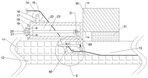
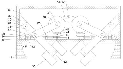
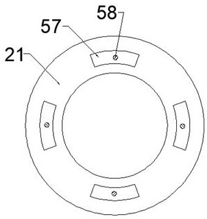
[0019] Combine below Figure 1-6 The present invention is described in detail, wherein, for the convenience of description, the orientations mentioned below are defined as follows: figure 1 The front, back, left, right, up, and down directions of the view direction are the same, figure 1 It is the front view of the device of the present invention, figure 1 The directions shown are consistent with the front, back, left, right, up, and down dire...


PUM


Abstract

The invention discloses a dragging type optical cable laying plough for laying an optical cable in a shallow soil layer. The plough comprises soil to be ploughed, a laying space is formed in the rightside of soil to be ploughed; the right side of the soil to be ploughed is abutted against a laying plough stress shell. A laying plough internal space is formed in the laying plough stress shell; theupper side face of the laying plough stress shell is fixedly connected with a pulling shell. The plough is high in compatibility, the plough can be pulled by an existing carrier, laying can be suspended when foreign matter exists on a preset laying path by setting protection measures, abrasion of the foreign matter to the optical cable is prevented, the service life is shortened, a manual buryinglink is omitted by setting a burying device, and the labor cost is saved.

Description

technical field [0001] The invention relates to the related fields of optical cables, in particular to a drag-type optical cable laying plow for laying optical cables in shallow soil layers. Background technique [0002] With the development of the economy, people have higher and higher requirements for information transmission. Therefore, optical cables are often laid on the land in use in cities. The traditional laying methods are mostly manual laying, and the construction and laying cannot be automated. The construction site has a negative impact on the surrounding traffic for a long time, so it is of great significance to improve the efficiency of laying optical cables. Contents of the invention [0003] The object of the present invention is to provide a towed optical cable laying plow for laying optical cables in shallow soil layers, so as to solve the problems raised in the above-mentioned background technology. [0004] In order to achieve the above object, the pr...

Claims


Application Information

Patent Timeline
Patent Type & Authority Applications(China)
IPC IPC(8): G02B6/50
CPCG02B6/50G02B6/504
Inventor 马付强
Owner 武汉长恒如工艺品有限公司
Why Eureka
Try Eureka