
Intersection signal-vehicle trajectory cooperative control method in vehicle-road cooperative environment

A technology of vehicle trajectory and vehicle-road coordination, which is applied to the traffic control system of road vehicles, traffic control systems, and control traffic signals, etc., and can solve problems such as vehicle conflicts, waste of green light time, and reduced intersection efficiency

Active Publication Date: 2020-09-25
TONGJI UNIV
View PDF8 Cites 21 Cited by
  • Summary
  • Abstract
  • Description
  • Claims
  • Application Information

AI Technical Summary

Problems solved by technology

At the same time, the green light interval also has an impact on the efficiency of the intersection. Too long green light intervals will lead to waste of invalid green light time and reduce the efficiency of the intersection.
At present, researchers at home and abroad have proposed many solutions for intersection control in a vehicle-road collaborative environment, but most of them adopt the method of simplifying the green light interval setting, such as setting the green light interval to 3s or 4s, although this method can be used to a certain extent. To improve the efficiency of intersection traffic, but it is easy to cause vehicle conflicts, especially during the signal switching period of the intersection, vehicle safety accidents are more likely to occur

Method used


Image

  • Intersection signal-vehicle trajectory cooperative control method in vehicle-road cooperative environment
  • Intersection signal-vehicle trajectory cooperative control method in vehicle-road cooperative environment
  • Intersection signal-vehicle trajectory cooperative control method in vehicle-road cooperative environment

Examples


Embodiment

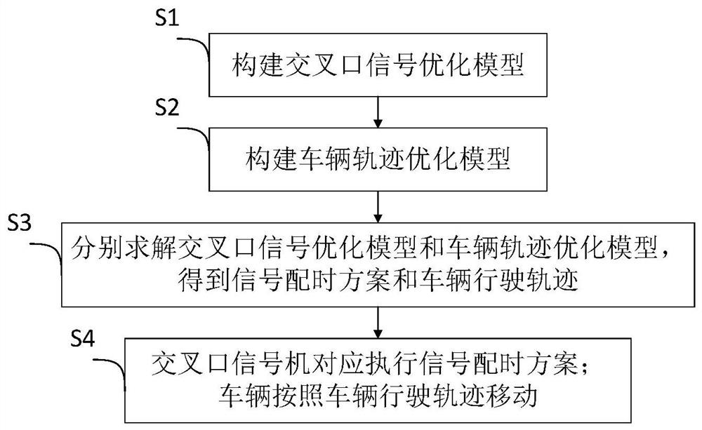
[0083] like figure 1 As shown, an intersection signal-vehicle trajectory cooperative control method in a vehicle cooperative environment includes the following steps:

[0084] S1. Construct an intersection signal optimization model. The objective function of the intersection signal optimization model is to minimize the average vehicle delay. The constraints include: green light duration constraints, green light interval constraints, vehicle arrival stop line state constraints, and vehicle passing through the intersection constraints;

[0085] S2. Build a vehicle trajectory optimization model. The objective function of the vehicle trajectory optimization model is to minimize vehicle fuel consumption, and the constraints include: vehicle dynamics constraints, vehicle speed constraints, vehicle acceleration constraints, vehicle distance constraints, and vehicle passing stop line state constraints;

[0086] S3. Respectively solve the intersection signal optimization model and the ...


PUM


Abstract

The invention relates to an intersection signal-vehicle trajectory cooperative control method in a vehicle-road cooperative environment. The method comprises the following steps: constructing an intersection signal optimization model; constructing a vehicle trajectory optimization model; solving the intersection signal optimization model and the vehicle trajectory optimization model respectively to obtain a signal timing scheme and a vehicle traveling trajectory, wherein the vehicle traveling trajectory comprises the positions and speeds of vehicles in an entrance lane and an intersection, theintersection annunciator correspondingly executes the signal timing scheme, and the vehicle moves according to the vehicle running track. Compared with the prior art, the method has the advantages that reasonable green light intervals can be dynamically designed according to the size characteristics of different intersections, and vehicle conflicts caused by breaking of the green light intervalsand effective green light time waste caused by overlong green light intervals are avoided; and meanwhile, the driving tracks of the vehicles in the entrance lanes and the intersections are optimized,so that the safety in the signal switching period is guaranteed, and the passing efficiency and safety of the intersections are effectively improved.

Description

technical field [0001] The invention relates to the technical field of intelligent traffic control, in particular to an intersection signal-vehicle trajectory coordinated control method in a vehicle-road coordinated environment. Background technique [0002] In the networked environment, the V2I (vehicle-to-infrastructure, vehicle-to-infrastructure) communication system can provide more detailed data for intersection control: including vehicle position, speed, etc., and these data can be used for intersection signal timing. optimization. In the intersection signal control process, the green light interval is an important parameter. The green light interval refers to the time interval between two conflicting traffic flows at signalized intersections from the end of the green light of the previous traffic flow that lost the right of way to the start of the green light of the next traffic flow that has the right of way. [0003] The purpose of setting the green light interval...

Claims


Application Information

Patent Timeline
IPC IPC(8): G08G1/08G08G1/095G08G1/01G08G1/0968G06F30/20G06F111/06G06F111/04
CPCG08G1/0125G08G1/08G08G1/095G08G1/096816G06F30/20G06F2111/04G06F2111/06Y02T10/40
Inventor 杨晓光龙可可马成元赖金涛
Owner TONGJI UNIV
Learn More