
A moving contact base body and a three-position isolating grounding switch

A technology for isolating grounding switches and moving contacts, which is applied in the direction of grounding switches, electric switches, air switch components, etc., can solve the problems of poor conductivity and reliability, and achieve the goal of improving reliability, reliability and stability Effect

Active Publication Date: 2021-11-16
HENAN PINGGAO ELECTRIC +2
View PDF8 Cites 0 Cited by
  • Summary
  • Abstract
  • Description
  • Claims
  • Application Information

AI Technical Summary

Problems solved by technology

[0005] The purpose of the present invention is to provide a three-position isolating grounding switch to solve the problem of the stability and reliability of the sliding conductive contact between the moving contact and the moving contact seat in the existing three-positioning isolating grounding switch as described above. The technical problem of poor performance; the purpose of the present invention is also to provide a movable contact base, which is suitable for the three-position isolating grounding switch of the present invention, and ensures stable and reliable conductive contact between the movable contact and the movable contact seat when in use.

Method used


Image

  • A moving contact base body and a three-position isolating grounding switch
  • A moving contact base body and a three-position isolating grounding switch
  • A moving contact base body and a three-position isolating grounding switch

Examples


Embodiment 1

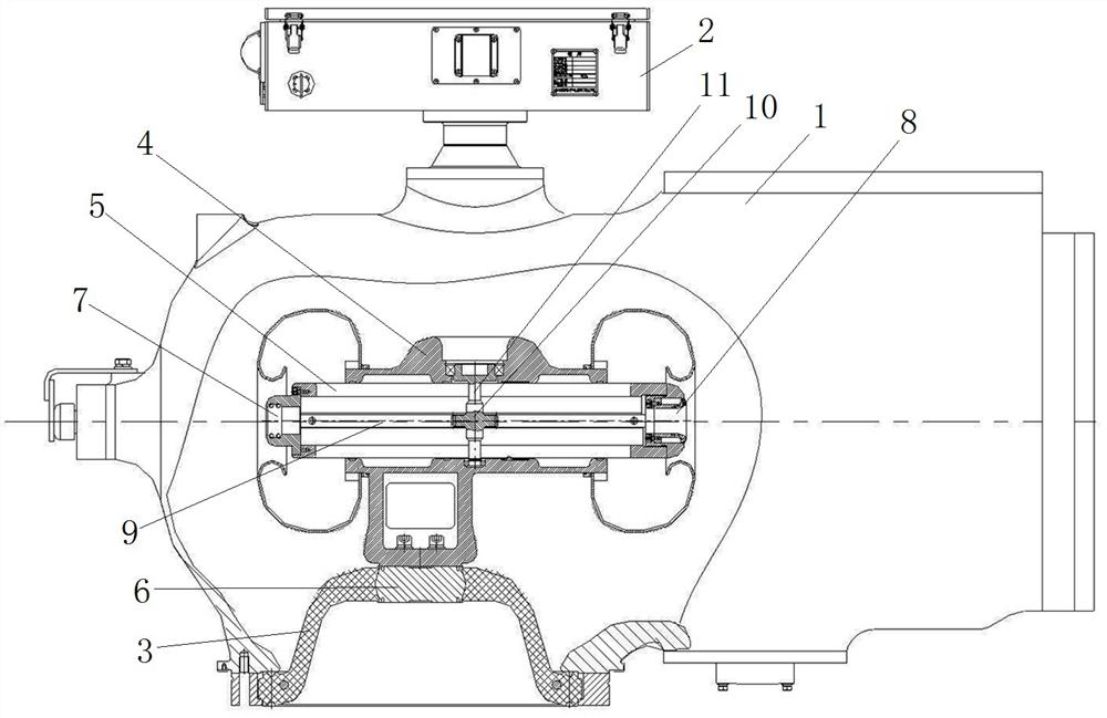
[0050] Such as figure 1 As shown, the three-position isolation and grounding switch includes a housing 1 and an operating mechanism 2 connected to the housing 1. The housing 1 is a hollow cavity, and a basin-type insulator 3 is sealed and installed on the housing 1. There is a moving contact assembly fixedly connected with the pot insulator 3.

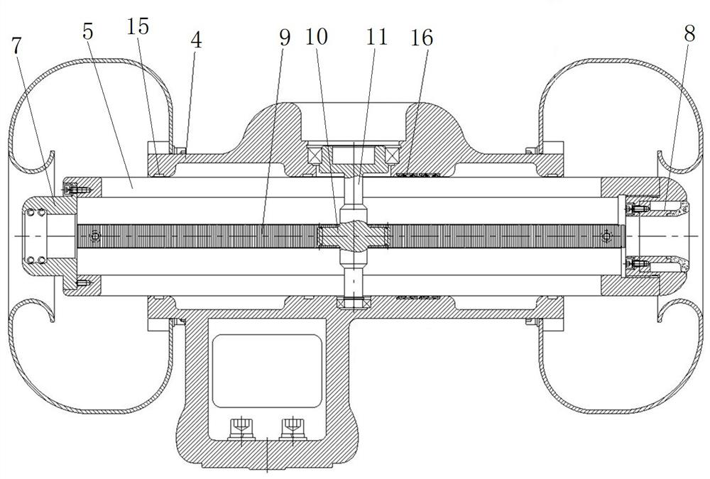
[0051] In this example, if figure 2 As shown, the moving contact assembly includes a moving contact seat 4 and a moving contact. The moving contact seat 4 is fixed on the pot insulator 3 for conductive connection with the center insert 6 at the center of the pot insulator 3 . The moving contact seat 4 has an internal guiding channel, and the moving contact is installed in the guiding channel, and can be guided and moved relative to the moving contact seat 4 under the driving action of the operating mechanism 2 .

[0052] In this example, if figure 1 and figure 2 As shown, a grounding static contact and an isolation static contact...

specific Embodiment 2

[0063]The difference between it and the specific embodiment 1 is that in order to improve the conductive connection between the moving contact seat and the moving contact, contact fingers are installed between the moving contact base and the moving contact seat on both sides of the gear shaft, and Both ends of the first elongated hole are provided with guide surfaces, which are used to make the contact fingers pass through the corresponding ends of the first elongated hole smoothly when the moving contact base moves towards the static contacts at both ends, which helps to make the contact The smooth compression of the fingers can reduce the probability of the fingers being stuck, damaged or scratched by the fingers, and helps to ensure the normal operation of the three-position isolating earthing switch.

[0064] In this embodiment, the circumferential ends of the contact fingers near the grounded static contact are respectively located on both sides of the notch in the width d...

specific Embodiment 3

[0066] The difference from the specific embodiment 1 is that the contact fingers that realize the conductive contact between the moving contact base and the moving contact seat are spring contact fingers, the spring contact fingers are arranged around the outer peripheral surface of the moving contact base, and the spring contact fingers bypass the first One slotted hole and the second slotted hole, guide surfaces are provided at the ends of the first slotted hole and the second slotted hole close to the isolating static contact, so as to guide the spring contacts to pass through the first slotted hole and the second slotted hole end, and guide the spring finger to compress when the spring finger passes over the end of the first elongated hole and the end of the second elongated hole.


PUM


Abstract

The invention relates to the technical field of electrical equipment, in particular to a moving contact base body and a three-position isolating grounding switch. The base body of the moving contact is a slender tubular structure, and there are two long holes arranged opposite to each other on the tube wall. The extending direction of the long holes is consistent with the length direction of the moving contact base body. The guide surface is used to guide the contact finger installed on the contact seat to slide over to make the contact finger smoothly compressed. The guide surface includes a side guide surface connected to the side wall of the long hole and an end connected to the end wall of the long hole. When the moving contact base moves relative to the moving contact base and the contact finger passes through the end of the long hole, the guiding surface can guide the finger to slide through the end of the long hole, and the end guiding surface and the side guiding face The compression of the contact finger has a guiding effect, which can realize the smooth compression of the contact finger. The above-mentioned moving contact base is used in the three-position isolation grounding switch, which can improve the reliability of the conductive contact between the moving contact and the moving contact seat during the relative sliding process. and stability.

Description

technical field [0001] The invention relates to the technical field of electrical equipment, in particular to a moving contact base body and a three-position isolating grounding switch. Background technique [0002] The three-position isolating and grounding switch integrates the functions of the isolating switch and the grounding switch, and has the advantages of low cost, small size, and high safety, and gradually replaces the traditional separately arranged isolating switch and grounding switch. [0003] The invention patent application document with the authorized announcement number CN102254730B and the authorized announcement date of November 27, 2013 discloses a three-position isolation grounding switch. The three-position isolation grounding switch includes a housing with a movable contact The head seat and the moving contact seat have a guide channel, and the movable guide in the guide channel is equipped with a moving contact. The two ends of the guide channel of t...

Claims


Application Information

Patent Timeline
Patent Type & Authority Patents(China)
IPC IPC(8): H01H31/00H01H31/02
CPCH01H31/003H01H31/026
Inventor 王小东朱传运张皓祺李伟强董斌黄鑫秦泳
Owner HENAN PINGGAO ELECTRIC
Learn More