A kind of Lunebo lens and the production method of the Lunebo lens

A technology of Lunberg lens and production method, which is applied to antennas, electrical components, etc., can solve the problems of difficult to produce products, cumbersome production process, easy contact of metal fibers, etc., and achieve the effects of simple production process, reasonable design and convenient production.

Active Publication Date: 2021-09-24
GUANGDONG FUSHUN TIANJI COMM CO LTD
View PDF5 Cites 0 Cited by
  • Summary
  • Abstract
  • Description
  • Claims
  • Application Information

AI Technical Summary

Problems solved by technology

[0002] At present, most Lunber lenses on the market are composed of multiple dielectric layers wrapped in layers, and each dielectric layer is composed of a number of fine particles with metal fibers bonded together by glue. When forming the dielectric layer Since the direction of the metal fibers in each particle cannot be kept consistent, the metal fibers on two adjacent particles in the Lunberg lens after production are easy to contact and conduct, which affects the dielectric constant of the Lunberg lens. , and the design of the entire Lunberg lens is formed by bonding particles with metal fibers with an adhesive. produce standardized products

Method used


Image

  • A kind of Lunebo lens and the production method of the Lunebo lens
  • A kind of Lunebo lens and the production method of the Lunebo lens
  • A kind of Lunebo lens and the production method of the Lunebo lens

Examples


Embodiment 1

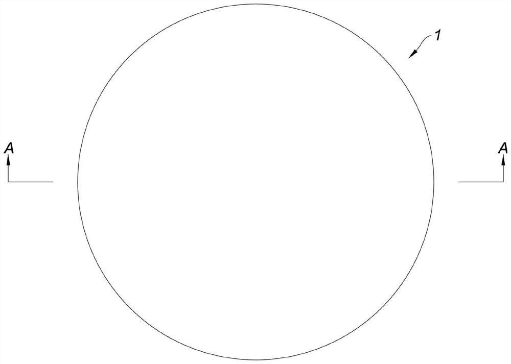
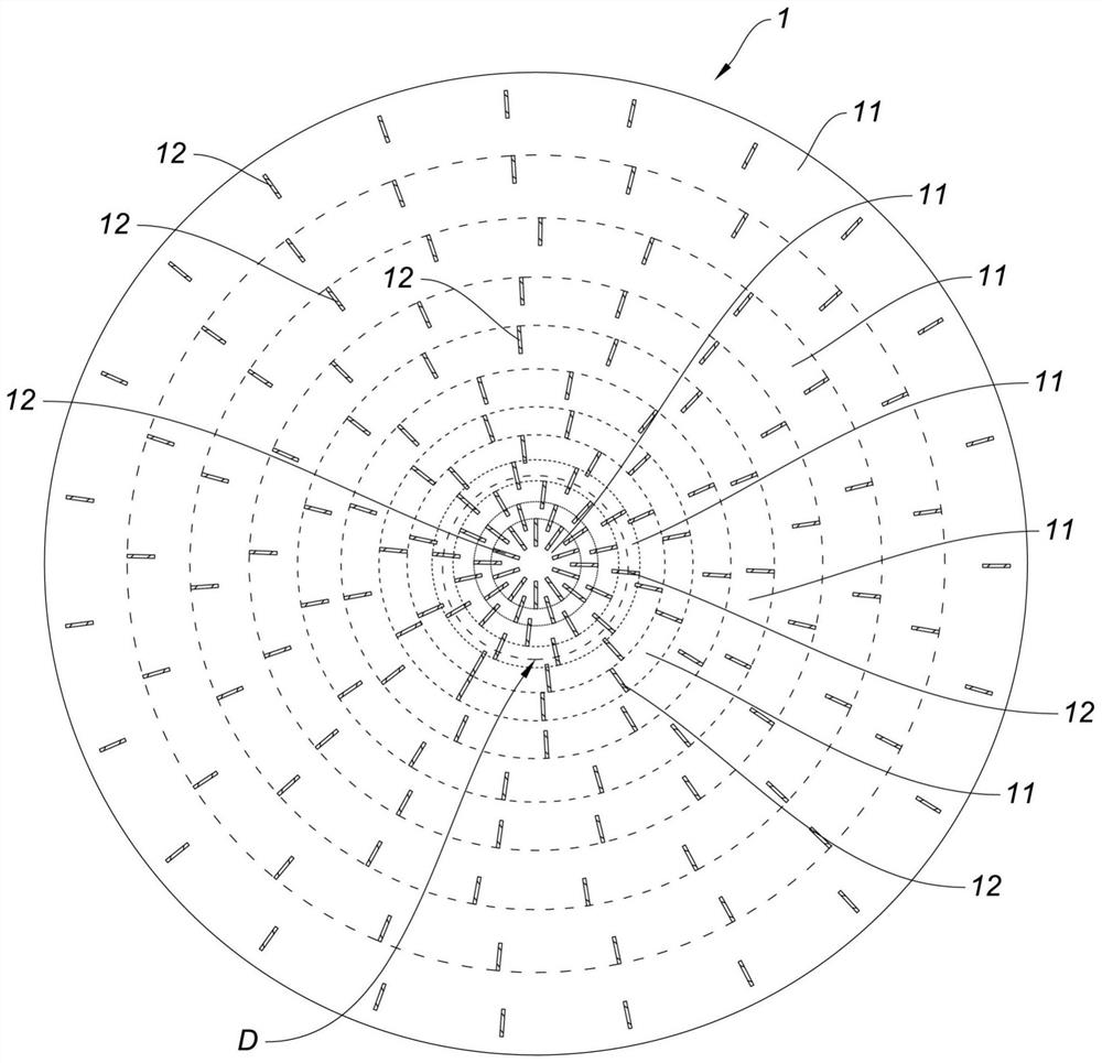
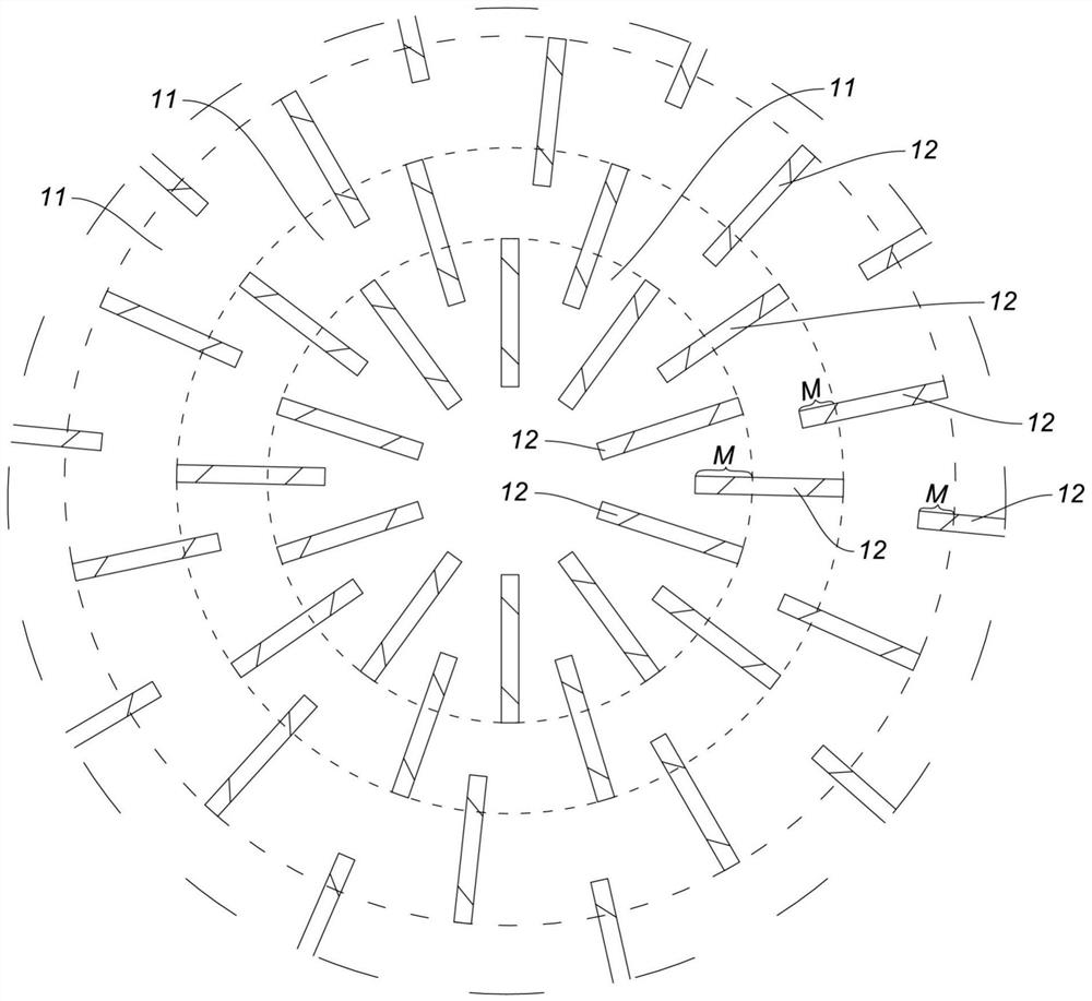
[0036] Such as figure 1 , figure 2 , image 3 As shown, the present embodiment is a Lunberg lens, including a main body 1, the main body 1 is made of insulating material, an electromagnetic wave incident area is formed on the outer surface of the main body 1, and an electromagnetic wave incident area is formed from the center of the main body 1 to the electromagnetic wave incident area. Several layers of conductive material layers 11 are arranged in sequence, and each conductive material layer 11 includes a plurality of conductive wires 12 evenly inserted and embedded in the body 1; the conductive wires 12 in each layer of conductive material layer 11 are conductive wires of the same length , between two adjacent conductive wires 12 in each conductive material layer 11 are blocked by the insulating material constituting the body 1; between two adjacent conductive material layers 11: the conductive wire of one layer of conductive material layer 11 12 and the conductive threa...

Embodiment 2

[0040] The difference between this embodiment and embodiment 1 is: as Figure 4 , Figure 5 As shown, the body 2 is a cylindrical structure, the center of the body 2 is its axis a, the side of the body 2 is the electromagnetic wave injection area, and the conductive wires 22 of each conductive material layer 21 are all directed to the axis a of the body 2 . In this embodiment, the main body 2 is designed as a cylindrical structure to meet the needs of customers for different application scenarios.

Embodiment 3

[0042] The difference between this embodiment and embodiment 1 is: as Image 6 , Figure 7 As shown, the body 3 is an ellipsoid structure, the center of the body 3 is its major axis b, the outer surface between the two focal points on the body 3 is the electromagnetic wave injection area, and the two focal points on the body 3 are points F1 and At point F2 , the conductive filaments 32 of each conductive material layer 31 are directed to the long axis b of the body 3 . In this embodiment, the main body 3 is designed as an ellipsoid structure to meet the needs of customers for different application scenarios.


PUM


Abstract

The invention relates to a Lunberg lens, which comprises a body made of insulating material, on which an electromagnetic wave injection area is formed, and several conductive material layers are sequentially arranged between the center of the body and the electromagnetic wave injection area, and each conductive material layer includes a uniform Insert several conductive wires buried on the body; the two adjacent conductive wires in each conductive material layer are blocked by insulating materials; the conductive wires of the adjacent two layers of conductive material layers are also insulated Material barrier; the closer to the center of the body, the denser the conductive filaments in the conductive material layer are arranged. The Lumber lens has the characteristics of convenient production, no conduction between conductive threads, and standardized production can be realized. The invention also provides a production method of the Lunbo lens. The production method of the Lunbo lens has the characteristics of simple production process, no conduction between conductive wires after production is completed, and standardized production can be realized.

Description

technical field [0001] The invention relates to the technical field of antennas, in particular to a Luneberg lens; the invention also relates to a production method of a Luneburg lens. Background technique [0002] At present, most Lunber lenses on the market are composed of multiple dielectric layers wrapped in layers, and each dielectric layer is composed of a number of fine particles with metal fibers bonded together by glue. When forming the dielectric layer Since the direction of the metal fibers in each particle cannot be kept consistent, the metal fibers on two adjacent particles in the Lunberg lens after production are easy to contact and conduct, which affects the dielectric constant of the Lunberg lens. , and the design of the entire Lunberg lens is formed by bonding the particles with metal fibers with an adhesive. Produce standardized products. Contents of the invention [0003] The purpose of the present invention is to provide a Lunberg lens, which has the ...

Claims


Application Information

Patent Timeline
Patent Type & Authority Patents(China)
IPC IPC(8): H01Q15/02
CPCH01Q15/02
Inventor 郑洪振芦永超尚春辉
Owner GUANGDONG FUSHUN TIANJI COMM CO LTD
Why Eureka
Try Eureka