Rapid straightening cutting equipment

A cutting equipment and straightening technology, which is applied in the field of fast straightening cutting equipment, can solve problems such as damage to pressing parts, inability to buffer the pressing parts, and affect adjustment and transportation, so as to prolong service life, reduce manual adjustment, and improve work efficiency. efficiency effect

Inactive Publication Date: 2020-09-29
QINGYUAN DINGXINGTAI MASCH EQUIP CO LTD
View PDF0 Cites 2 Cited by
  • Summary
  • Abstract
  • Description
  • Claims
  • Application Information

AI Technical Summary

Problems solved by technology

Generally, after the steel bars are formed in the iron and steel plant, most of the steel bars will be rolled into a circle and bundled together for the convenience of transportation. Like this, the steel bar straightening machine must be used to straighten the steel bars during construction on the site. The existing In the steel bar straightening machine, there are multiple relative pressure rollers, and the steel bar is transmitted from the middle of the pressure wheel. During the transmission process, the pressure wheel squeezes the steel bar in turn, so as to straighten the bent part of the steel bar, and then according to The length of the required steel bar is cut; most of the existing straightening equipment uses the screw to adjust the distance between the pressure rollers, and the compression part cannot be buffered. If the steel bar is bent irregularly, this method may It will cause the forced fit between the pressing part and the steel bar, affect the adjustment and transportation, and even cause damage to the pressing part

Method used


Image

  • Rapid straightening cutting equipment
  • Rapid straightening cutting equipment
  • Rapid straightening cutting equipment

Examples


Embodiment Construction

[0022] The technical solutions of the present invention will be further described below in conjunction with the accompanying drawings and through specific implementation methods.

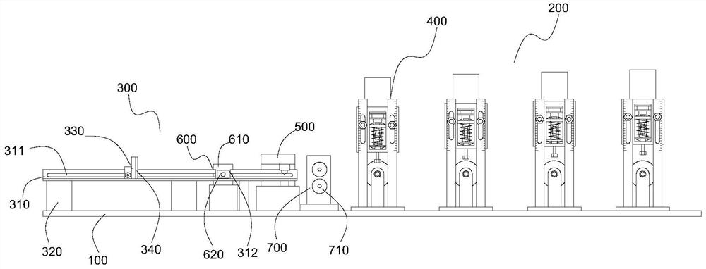
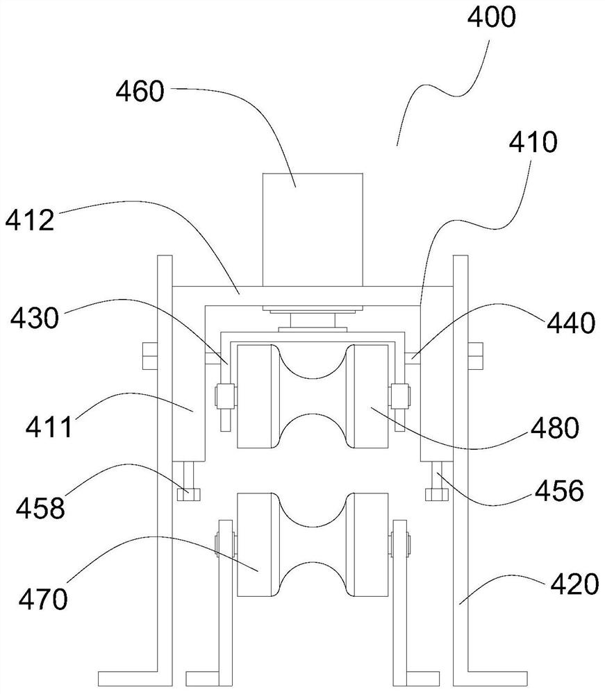
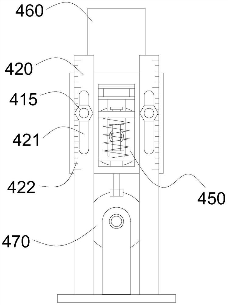
[0023] Such as Figure 1 to Figure 4 As shown, the rapid straightening and cutting equipment provided by the specific embodiment of the present invention includes a base plate 100, a straightening part 200 and a cutting part 300 installed on the base plate 100, and the straightening part 200 includes a plurality of The guide roller structure 400, the guide roller structure 400 includes a first installation frame 410 and an opposite stand 420, the first installation frame 410 is installed between the two stands 420, and the installation height can be Adjust; the first installation frame 410 includes two opposite vertical plates 411 and a horizontal plate 412 fixed on the top of the vertical plate 411, and a second installation frame 430 is arranged between the two vertical plates 411. The inner side...


PUM


Abstract

The invention discloses rapid straightening cutting equipment. The equipment comprises a straightening part and a cutting part, wherein the straightening part comprises a plurality of guide compression roller structures arranged in sequence, a first roller body and a hydraulic cylinder for driving the first roller body to move are arranged on each guide compression roller structure, and the firstroller bodies are secondarily supported through a pressure regulating structure; the cutting part comprises a bearing groove, a cutting machine is arranged at the end, close to the straightening part,of the bearing groove, a pushing structure is arranged on the side, away from the straightening part, of the cutting machine, and the pushing structure is used for pushing cut steel bars away from the bearing groove; a double-roller pressing and conveying mechanism is arranged on one side, close to the straightening part, of the cutting machine; according to the equipment, the steel bars can be rapidly pressed, straightened and cut, the straightening distance of a pressed and straightened portion can be driven and adjusted by a driving piece, manual operation is reduced, and the adjusting efficiency is improved; and the pressing and straightening portion has a certain buffering effect, so that the bent steel bar can be prevented from being in hard fit with a pressing piece, the pressing piece is prevented from being damaged, and the service life of the equipment is prolonged.

Description

technical field [0001] The invention relates to the technical field of straightening equipment, in particular to a fast straightening and cutting equipment. Background technique [0002] In reinforced concrete, steel bars are indispensable frame materials, and the processing and forming of steel bars directly affect the strength and engineering quality of reinforced concrete structures. Generally, after the steel bars are formed in the iron and steel plant, most of the steel bars will be rolled into a circle and bundled together for the convenience of transportation. Like this, the steel bar straightening machine must be used to straighten the steel bars during construction on the site. The existing In the steel bar straightening machine, there are multiple relative pressure rollers, and the steel bar is transmitted from the middle of the pressure wheel. During the transmission process, the pressure wheel squeezes the steel bar in turn, so as to straighten the bent part of t...

Claims


Application Information

Patent Timeline
Patent Type & Authority Applications(China)
IPC IPC(8): B21F1/02B21F11/00B21F23/00
CPCB21F1/026B21F11/00B21F23/00
Inventor 卢健华
Owner QINGYUAN DINGXINGTAI MASCH EQUIP CO LTD
Why Eureka
Try Eureka