
Nut conveying and positioning method for nut riveting

A positioning method and technology of riveting and pressing screws, which is applied in the field of riveting presses, can solve problems such as inaccurate positioning of nuts, and achieve the effects of reducing friction, smooth movement, and accurate position

Inactive Publication Date: 2020-09-29
刘天芳
View PDF8 Cites 2 Cited by
  • Summary
  • Abstract
  • Description
  • Claims
  • Application Information

AI Technical Summary

Problems solved by technology

[0005] The purpose of the present invention is to provide a nut delivery and positioning method for riveting nuts that can be accurately positioned in order to solve the problem that some traditional riveting presses easily cause inaccurate nut positioning

Method used


Image

  • Nut conveying and positioning method for nut riveting
  • Nut conveying and positioning method for nut riveting
  • Nut conveying and positioning method for nut riveting

Examples


Embodiment 1

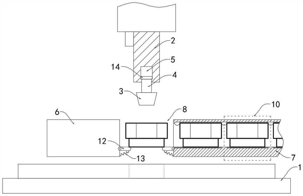
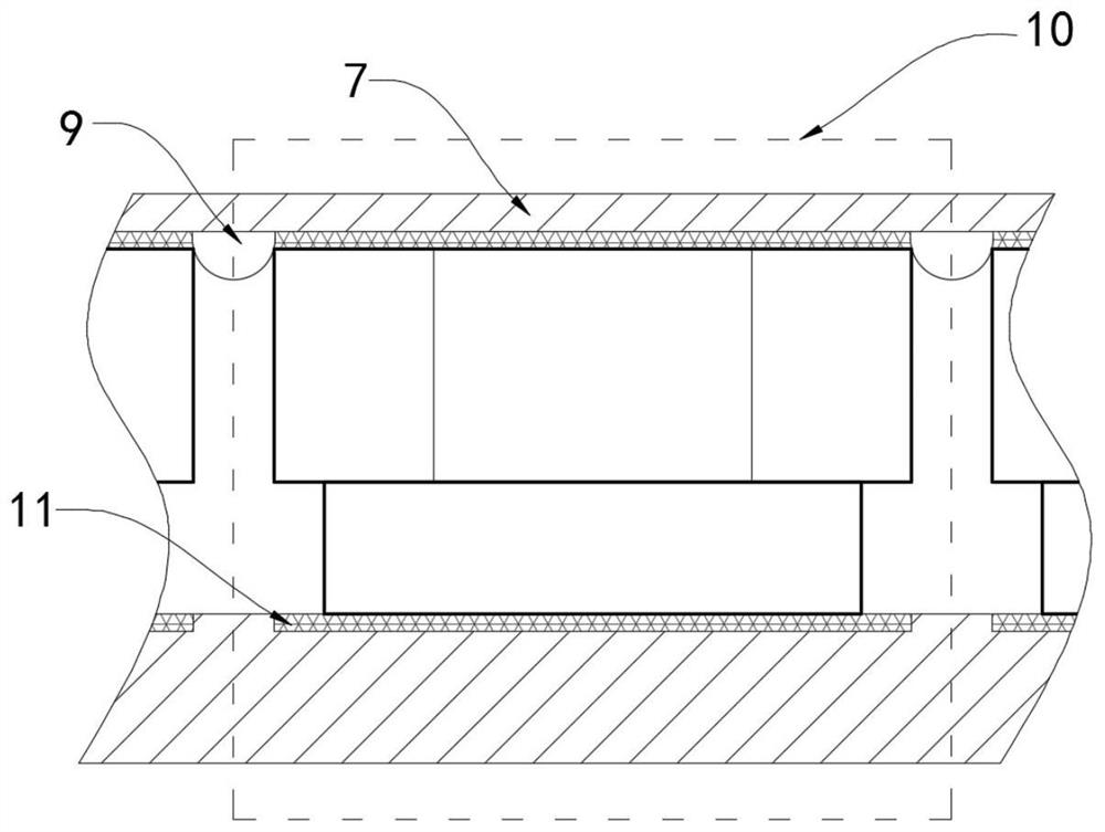
[0028] like Figure 1-2 As shown, a nut delivery and positioning method of a riveting nut, the specific delivery and positioning method is as follows:

[0029] S1, feeding, put a plurality of nuts into the delivery cylinder 7 in sequence, each nut is placed in a conductive unit 10 and forms a conductive circuit with the conductive plates 11 on the upper and lower side walls of the conductive unit 10;

[0030] S2, conveying, when the magnetic positioning block 3 is close to the port of the delivery cylinder 7, the nut will move into the positioning port 8 under the common gravitational force of the magnetic positioning block 3 and the magnetic fixing block 6;

[0031] S3, positioning, the riveting head 2 moves downward for a certain distance, the magnetic positioning block 3 at its lower end will first contact the nut, and when the nut position is accurate, the magnetic fixing block 6 will smoothly enter the through hole of the nut;

[0032] S4, riveting, after the positioning...

Embodiment 2

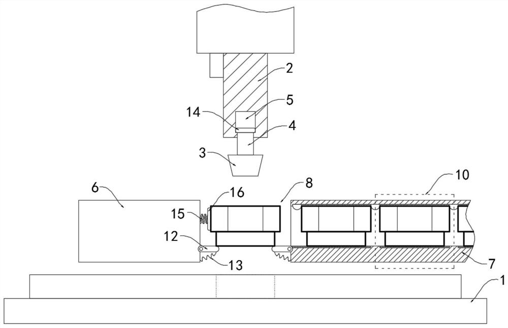
[0047] like Figure 3-4 As shown, the difference between this embodiment and Embodiment 1 is that the side wall of the magnetic fixing block 6 located in the positioning opening 8 is fixedly connected with the positioning plate 16 through the induction coil 15. It is worth mentioning that the inner side of the delivery cylinder 7 A plurality of rollers 17 are fixedly installed on the wall.

[0048] In this embodiment, when the nut moves to the positioning port 8 under the gravitational force of the magnetic positioning block 3 and the magnetic fixing block 6, since the nut is electrified at this time and has magnetism, it can be known from Lenz's law that the magnetic field of the induced current always Blocking the change of the magnetic flux that causes the induced current, the magnetic nut will decelerate under the repulsion of the induction coil 15 when it is close to the induction coil 15, which can prevent the nut from colliding with the positioning plate 16 at a relativ...


PUM


Abstract

The invention belongs to the field of riveting machines, and particularly relates to a nut conveying and positioning method for nut riveting. The conveying and positioning method specifically comprises the following steps of feeding, conveying, positioning and riveting; a riveting machine is further involved in the conveying and positioning method and comprises a placement platform and a rivetinghead with the side wall being provided with a controller; the lower end of the riveting head is provided with a magnetic positioning block internally provided with a sensor, the upper side wall of themagnetic positioning block is fixedly connected with a connecting rod, and the upper end of the connecting rod extends into the riveting head; and the riveting head is internally provided with a sliding groove matched with the connecting rod, and a magnetic fixing block and a conveying tube which are arranged horizontally are arranged between a riveting head and the placement platform. By arranging an induction coil, in the process that a nut moves to a positioning opening under the attractive effects of the magnetic positioning block and the magnetic fixing block, the nut is powered on and has magnetism at the moment, thus the nut decelerates under the effect of the Lenz's law when getting close to the induction coil, and the nut can be prevented from hitting a positioning plate at a high speed.

Description

technical field [0001] The invention belongs to the field of riveting presses, in particular to a nut delivery and positioning method for riveting nuts. Background technique [0002] The connection methods of the workpiece include screw connection, key connection and pin connection, etc. Riveting is also an important part of it. Riveting needs to be carried out by a riveting press. During the processing, two or more layers of boards of different materials and different thicknesses can be connected. [0003] When some traditional riveting machines are riveting nuts, it is necessary to continuously place the nuts under the riveting head manually to realize the continuous operation of the device, which not only easily hurts the hands of the staff, but also It is also easy to locate inaccurately during the process, which affects the processing quality. Moreover, although most traditional riveting presses are equipped with automatic conveying and positioning devices, the structu...

Claims


Application Information

Patent Timeline
IPC IPC(8): B21J15/32B21J15/38B21J15/10
CPCB21J15/10B21J15/32B21J15/38
Inventor 刘天芳杨伟
Owner 刘天芳
Learn More