Hydraulic suspension structure

A technology of hydraulic suspension and liquid cavity, which is applied in the direction of power plant, jet propulsion device, internal combustion propulsion device, etc. It can solve the problems of slow response speed of vibration reduction, poor sealing effect, easy leakage of liquid, etc., and achieve the effect of vibration reduction and energy absorption Strong, good sealing performance

Active Publication Date: 2020-09-29
ZHEJIANG LEAPMOTOR TECH CO LTD
View PDF11 Cites 1 Cited by
  • Summary
  • Abstract
  • Description
  • Claims
  • Application Information

AI Technical Summary

Problems solved by technology

[0004] The present invention overcomes the shortcomings of existing hydraulic mounts, such as poor vibration reduction effect, slow vibration reduction response speed, poor se

Method used


Image

  • Hydraulic suspension structure
  • Hydraulic suspension structure
  • Hydraulic suspension structure

Examples


Embodiment 1

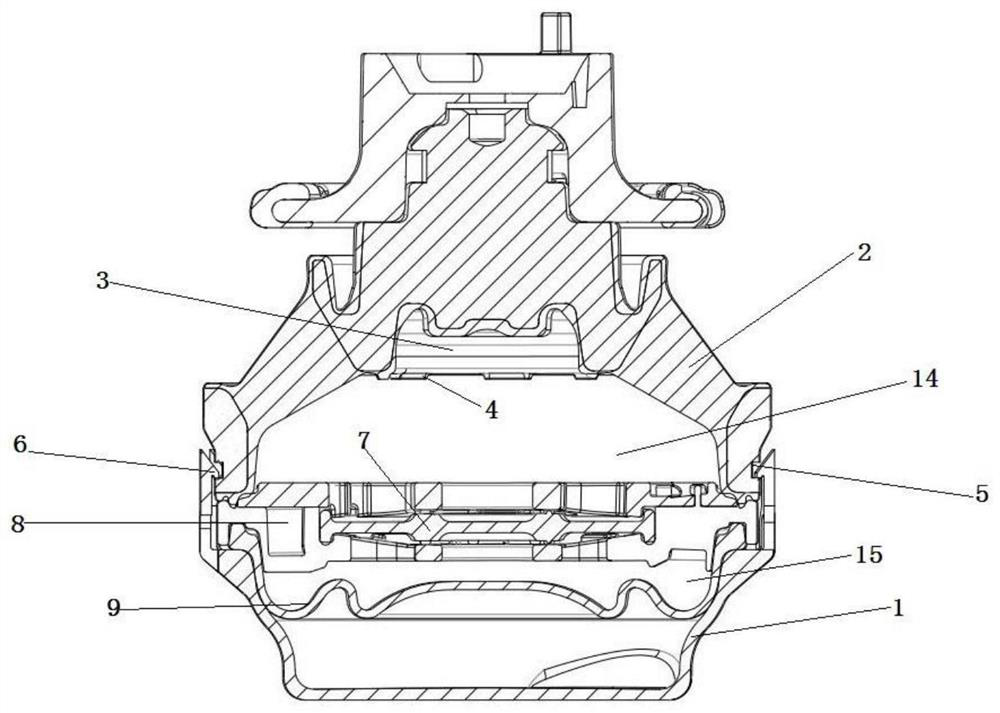
[0025] Such as figure 1 As shown, a hydraulic suspension structure, including the base plate bracket 1, the main spring rubber 2, the upper liquid chamber 14 and the lower liquid chamber 15, the main spring rubber 1, the upper liquid chamber 14 and the lower liquid chamber 15 are arranged in sequence from top to bottom , the inside of the main spring rubber 2 includes a main spring inner frame 3 communicating with the upper liquid chamber, and the main spring inner frame 3 is provided with a convex strip 4 adjacent to the upper liquid chamber 14, and the convex strip 4 is circumferentially arranged on the inner side wall of the main spring rubber 2 Above, the bottom of the main spring rubber 2 is provided with a first annular groove 5, the first annular groove 5 is arranged on the outer wall of the main spring rubber 2, and the upper edge of the bottom plate bracket 1 is provided with a groove that matches the first annular groove 5. The ring buckle 6 is an interference fit wi...

Embodiment 2

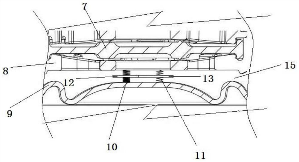
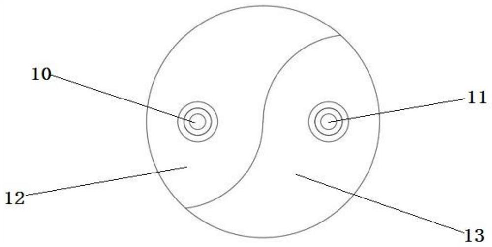
[0028] Based on Example 1, such as figure 2 , image 3 As shown, the bottom of the lower liquid chamber is a bowl-mounted lower diaphragm 9, the lower diaphragm 9 and the decoupling plate 8 form a lower liquid chamber, and a vertical arrangement is arranged between the lower diaphragm 9 and the decoupling membrane 8. The rotary spring is provided with a horizontal partition in the middle of the rotary spring. When the rotary spring is compressed, the partition rotates around the spring. The rotating springs include left rotating springs 10 and right rotating springs 11 arranged side by side. The left rotating springs 10 and right rotating springs 11 have different elastic coefficients. 12. The partition provided in the middle of the right rotation spring 11 is the second partition 13, and the cross-sections of the first partition 12 and the second partition 13 are respectively in the shape of yin and yang fish. Both the first partition 12 and the second partition 13 are mad...


PUM


Abstract

The invention discloses a hydraulic suspension structure, and aims to provide the hydraulic suspension structure with stronger shock absorption and energy absorption effects and better sealing performance. The structure comprises a bottom plate bracket, a main spring rubber, an upper liquid cavity and a lower liquid cavity. The main spring rubber, the upper liquid cavity and the lower liquid cavity are sequentially arranged from top to bottom. An opening connected with the upper liquid cavity is arranged in the main spring rubber, a protruding strip is arranged in the opening, the protruding strip is arranged on an inner side wall of the main spring rubber in a circumferential direction, a first annular groove is arranged in the bottom of the main spring rubber and formed in the outer sidewall of the main spring rubber, an annular buckle matched with the first annular groove is arranged on an upper edge of the bottom plate bracket, and the annular buckle is in interference fit with the first annular groove. By the adoption of the design, a problem that a dynamic hardening frequency of hydraulic suspension is too low can be solved, a liquid seal percent of pass is increased, and reliability of the hydraulic suspension is effectively improved.

Description

technical field [0001] The invention relates to the technical field of automobile engine vibration reduction, in particular to a hydraulic mount structure. Background technique [0002] At present, the second-generation passive hydraulic mount structure is commonly used in automobiles, and its dynamic stiffness hardening frequency is still too low, resulting in high frequency dynamic stiffness and poor NVH (NOISE noise, VIBRATION vibration, HARSHNESS acoustic-vibration roughness) performance. Moreover, the structure of the liquid seal of the hydraulic mount is relatively complicated, and it is easy to leak liquid, and the qualified rate is low. [0003] Chinese Patent Publication No. CN202029688, published on November 09, 2011, the name of the invention is hydraulic mount, the application discloses a hydraulic mount, which includes an upper frame and a lower frame adapted to the upper frame , the upper frame and the lower frame form a chamber; a rubber body accommodated in ...

Claims


Application Information

Patent Timeline
IPC IPC(8): B60K5/12F16F13/08F16F13/30F16F9/32F16F9/34
CPCB60K5/1208F16F9/3207F16F9/34F16F13/085F16F13/305
Inventor 李建华杨志伟季明孙钢宫静董炜
Owner ZHEJIANG LEAPMOTOR TECH CO LTD
Why Eureka
Try Eureka