Washing machine

A technology for washing machines and washing tubs, applied in the field of washing machines, which can solve the problems of increasing production costs and use costs, occupying machine volume, and failure to achieve capacity expansion, etc., and achieves the effects of simple structure, low cost, and high heating efficiency

Pending Publication Date: 2020-09-29
QINGDAO HAIER WASHING MASCH CO LTD +1
View PDF2 Cites 1 Cited by
  • Summary
  • Abstract
  • Description
  • Claims
  • Application Information

AI Technical Summary

Problems solved by technology

[0006] However, the above-mentioned first water heating method is difficult to control the temperature due to different water pressures, and the water inlet time is too long; while the second heating method needs to increase the production cost and use cost, and also takes up the energy in the machine. Volume, can not achieve the effect of expansion

Method used


Image

  • Washing machine
  • Washing machine
  • Washing machine

Examples


Embodiment 1

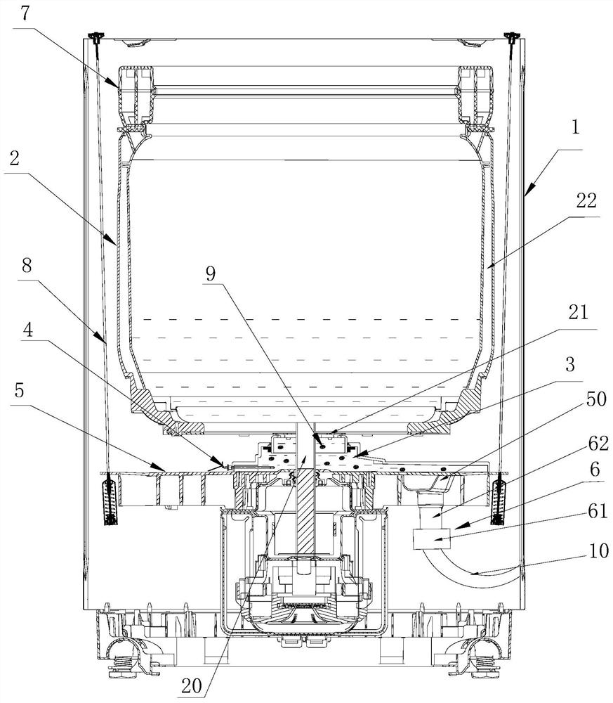
[0064] like figure 1 As shown, the heating unit 4 in this embodiment is arranged in the drain chamber 3 ; it is deviated from the bottom wall of the washing tub 2 directly below the first drain 21 and / or deviated directly above the second drain 50 .

[0065] The setting structure of the heating unit 4 deviated directly below the first water outlet 21 can prevent the damage of the heating unit 4 caused by the impact of the water flow on the heating unit 4 or the water leakage at the installation caused by the shaking of the heating unit 4 during drainage. The water inlet of the drainage component, that is, the setting structure directly above the second drainage outlet 50 can prevent the wire scraps from accumulating and winding on the heating unit 4 during drainage, which affects the heating efficiency and drainage speed.

Embodiment 2

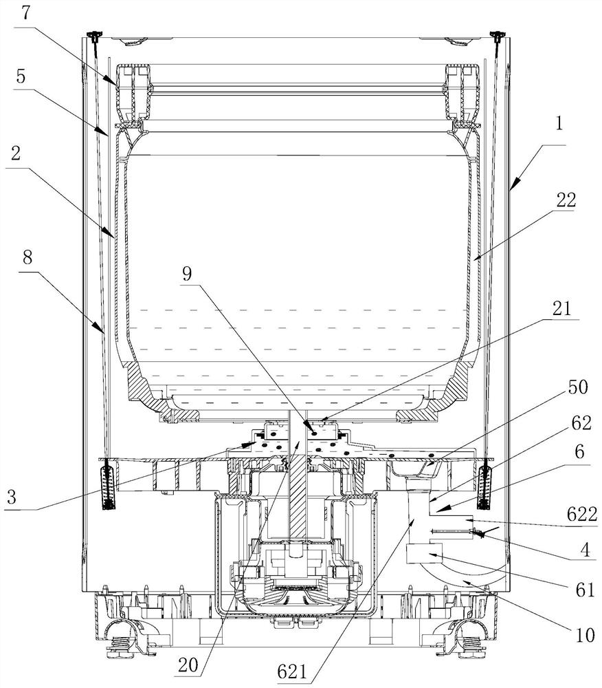
[0067] like figure 2 As shown, the drainage component 6 in this embodiment includes a drainage pipe 62 communicating with the second drainage port 50, and the heating unit 4 is arranged in the drainage pipe 62;

[0068] Preferably, the drainage pipeline 62 includes a main drainage pipeline 621 and a side branch pipeline 622 arranged on the side wall of the main pipeline 621 , and the heating unit 4 is arranged in the side branch pipeline 622 . This structure can reduce the impact of the drainage water flow on the heating unit, and at the same time prevent the heating unit from affecting the drainage speed.

[0069] Also preferably, a third filter unit (not shown in the figure) is provided at the connection between the main pipeline 621 and the bypass pipeline 622 to prevent the cleaning particles from entering the bypass pipeline 622. Preferably, the first filtering unit The three filter units can adopt the filter fence structure, which is beneficial to the passage of lint. ...

Embodiment 3

[0072] like Figure 5 As shown, the drainage chamber 3 in this embodiment includes a first cavity 31 and a second cavity 32 , and the first cavity 31 and the second cavity 32 are connected in a sealed manner so that they can rotate relative to each other. The peripheral wall of the first cavity 31 at least partially extends to the inside of the second cavity 32, and a sealing ring 33 is sleeved on the peripheral wall of the first cavity 31, and one side of the sealing ring 33 is connected to the first cavity. The body 31 is in sealing contact, and the other side is in sealing contact with the second cavity 32 .

[0073] Further, the sealing ring 33 is a skeleton oil seal, and is fixedly installed on the inner wall of the second cavity 32 close to the end of the first cavity 31 , the inner ring of the sealing ring 33 is in sliding contact with the outer peripheral wall of the first cavity 31 .

[0074]Preferably, the upper end of the first cavity 31 is sealed and connected wit...


PUM


Abstract

The invention discloses a washing machine. The washing machine comprises an outer shell, a wash bucket rotatably arranged in the outer shell, and a drainage chamber arranged below the wash bucket andcommunicating with the interior of the wash bucket, wherein the wash bucket is of a water-containing bucket structure; and the interior of the drainage chamber is provided with cleaning particles usedfor cleaning the inner wall of the chamber. The washing machine further comprises a water catcher for supporting the wash bucket. The water catcher is arranged outside the wash bucket. At least one part of the water catcher is arranged below the wash bucket. The water catcher is further provided with a draining component. The bucket bottom of the wash bucket is provided with a first drain outlet.The first drain outlet communicates with the draining component through the drainage chamber. The cleaning particles can move freely in the drainage chamber along with water flow. During the washingand/or rinsing stages, the water flow drives the cleaning particles to impact and rub the inner wall of the drainage chamber to clean the inner wall. The washing machine provided by the invention is simple in structure and low in cost and has the characteristic of self-cleaning.

Description

technical field [0001] The invention belongs to the field of washing equipment, and in particular relates to a washing machine. Background technique [0002] With the continuous development of washing machine technology, the washing machine has become more and more large-capacity, and when the washing machine gradually tends to large capacity, it will inevitably lead to the increase of the overall size of the washing machine. The water is distributed in the washing bucket and the outer bucket, that is, water is also distributed between the outer bucket and the washing bucket, and the water consumption is relatively large, resulting in waste of water resources; the existing washing machine dirt is easy to remain between the outer bucket and the washing bucket, thus Bacteria are bred and because water is distributed between the outer tub and the washing tub, the amount of detergent is also more, resulting in waste of detergent resources, which is not conducive to saving costs....

Claims


Application Information

Patent Timeline
Patent Type & Authority Applications(China)
IPC IPC(8): D06F35/00D06F39/04D06F39/08
CPCD06F35/008D06F39/04D06F39/083
Inventor 吕艳芬许升郝兴慧吕佩师
Owner QINGDAO HAIER WASHING MASCH CO LTD
Why Eureka
Try Eureka