
Novel prefabricated rail top air duct suitable for subway station

A technology for rail-top air ducts and subway stations, which is applied in pipeline layout, pipeline supports, mechanical equipment, etc. It can solve the problems of not considering professional interfaces, complicated construction procedures, and difficult to guarantee construction quality, and reduce the overall number of components and formwork. model, improve the integrity and look and feel quality, and facilitate the effect of mass production and promotion

Pending Publication Date: 2020-09-29
CHINA RAILWAY ERYUAN ENG GRP CO LTD
View PDF0 Cites 1 Cited by
  • Summary
  • Abstract
  • Description
  • Claims
  • Application Information

AI Technical Summary

Problems solved by technology

In the current conventional construction process, due to the influence of construction procedures or processes such as shield tunneling or formwork trolleys, the rail top air duct needs to enter the site for the second time after the construction of the middle plate is completed or even after the section tunnel is opened, and the steel bars of the rail top air duct and Concrete pouring requires complicated construction procedures and a long construction period, which leads to corresponding delays in subsequent procedures and a tight construction period. At the same time, the second pouring of the air duct on the rail top is pouring concrete from the holes reserved in the middle plate. The construction quality is difficult to guarantee, and vibrations often occur. Quality problems such as not compacting and exposed ribs will seriously affect the durability of this component
[0004] In order to solve the above problems, there are a small number of cases of using prefabricated rail top air ducts in the market at present, but there are the following problems, which lead to less popularization and application: 1. The prefabricated rail top air ducts adopt the overall prefabrication scheme of the section, resulting in large volume, heavy weight, and production 1. The transportation is inconvenient; 2. The vertical and line direction stress stability is poor; 3. The connection components of the prefabricated rail top air duct, the side wall and the middle plate have durability and waterproof problems; 4. The positioning of the components is difficult during installation; 5. The middle plate The conflict between embedded parts (such as bushings) and the rail top air duct has not been considered; 6. The follow-up professional interface issues have not been considered, such as: catenary installation interface, screen door installation interface, etc.

Method used


Image

  • Novel prefabricated rail top air duct suitable for subway station
  • Novel prefabricated rail top air duct suitable for subway station
  • Novel prefabricated rail top air duct suitable for subway station

Examples


Embodiment Construction

[0033] The present invention will be further described below in conjunction with the accompanying drawings and embodiments.

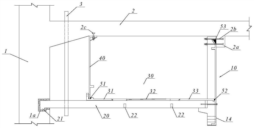
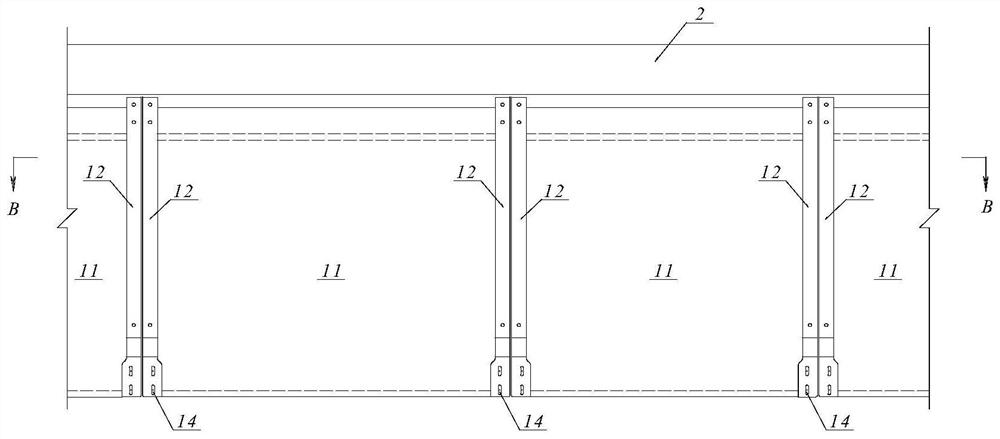
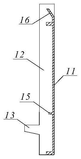
[0034] refer to figure 1 , a new type of prefabricated rail top air duct suitable for subway stations according to the present invention. The rail top air duct is formed by longitudinal butt joints of prefabricated air duct segments, and each prefabricated air duct segment forms a fixed connection with the station side wall 1 and the station middle plate 2 . The prefabricated air duct segments are assembled from side plate components 10 , cross beam components 20 , bottom plate components 30 and inner plate components 40 . The lateral sides of the side plate member 10 have vertically extending side plate columns 12, and the upper ends of the side plate columns 12 are fixed to the middle plate longitudinal beams 2a protruding downward from the bottom surface of the station middle plate 2 through the first embedded connecting member 2b. connect. The in...


PUM


Abstract

The invention relates to a novel prefabricated rail top air duct suitable for a subway station. The novel prefabricated rail top air duct suitable for the subway station aims to effectively avoid conflict between a middle plate embedded part and the rail top air duct, improve durability and construction efficiency of prefabricated parts and guarantee the construction quality. The novel prefabricated rail top air duct is characterized in that each prefabricated air duct section is formed by splicing a side plate component, a cross beam component, a bottom plate component and an inner side platecomponent, side plate columns extending vertically are arranged on the two transverse sides of each side plate component, the upper ends of the side plate columns are fixedly connected with a middleplate longitudinal beam protruding downwards from the bottom face of a station middle plate through first embedded connecting components, the inner end of each cross beam component is fixedly connected with a station side wall through a clamping structure, the outer end of each cross beam component is supported on the side plate columns and fixedly connected with the side plate columns through a connecting assembly, each bottom plate component is supported on the top faces of the cross beam components on the two sides and fixedly connected with the cross beam components through fixing components, the upper end of each inner side plate component is fixedly connected with the station middle plate through a second embedded connecting component, and the lower end of each inner side plate component is fixedly connected with the inner side of the corresponding bottom plate component through a bolt assembly.

Description

technical field [0001] The invention relates to subway stations and related underground structural engineering, in particular to a new type of fully prefabricated rail top air duct structure and assembly for subway stations. Background technique [0002] The track top air duct of the subway station is a kind of concrete box structure fixed on the bottom of the middle plate or on the side wall to form a rectangular air duct type to realize its functional requirements. [0003] The track top air duct is an essential internal component in a subway station. It mainly undertakes three functions. First, it needs environmental control and ventilation in the track area of ​​the station; second, the overhead catenary can be fixedly installed on the bottom surface of the track air duct; third , the upper part of the subway screen door or safety door is fixed and installed on the side of the rail top air duct. In the current conventional construction process, due to the influence of c...

Claims


Application Information

Patent Timeline
Patent Type & Authority Applications(China)
IPC IPC(8): F16L9/22F16L3/02F24F13/02E02D29/045
CPCF16L9/22F16L3/02E02D29/045F24F13/02
Inventor 刘岩王呼佳高鲲杨朋孙琮涵岑陈斌伍艺孙双祥朱宏海倪安斌喻波周明亮苟波赵品祥宋同伟杨征龙小艳易丹陈鼎李勇邹育陈宇翔伍伟林齐少轩卫军陈俊枭
Owner CHINA RAILWAY ERYUAN ENG GRP CO LTD
Learn More