Mechanical automatic controlled range constant pressure dredging valve

A mechanical, dredging valve technology, applied in mechanical equipment, valve details, valve devices, etc., can solve problems such as high cost, inability to adapt to the working environment, and unsuitable for long-distance transportation systems, to reduce the probability of pipe blockage, Good crushing effect

Active Publication Date: 2020-09-29
SUZHOU BATAO INFORMATION TECH CO LTD
View PDF5 Cites 1 Cited by
  • Summary
  • Abstract
  • Description
  • Claims
  • Application Information

AI Technical Summary

Problems solved by technology

[0002] During the material conveying process, especially at the front end of the valve, when the valve is closed, it is easy to accumulate material there. When the valve is opened again, due to the compression of the material, it will be blocked at the front end of the valve, resulting in blocked pipes. Most of the current solutions to the problem of blocked pipes are in the A high-pressure blow-assisted valve connected to the pipeline is installed on the material conveying pipeline. When the pipe is blocked, the device instantly fills a large amount of high-pressure gas into the conveying pipeline to blow away the blocked material and make the pipe unblocked. Both require an independent detection device to detect the phenomenon of material blockage and increase the pressure in time, and to control the blowing of high-pressure gas to remove the blockage. However, the above-mentioned method requires electrical components for detection and control, and may not be able to adapt to the harsh working environment. Therefore, The invention with the application number CN201510840704.4 provides a pneumatic automatic dredging valve, which has the advantages of simple structure and convenient processing and assembly, but this solution still needs to use an external booster device for boosting, and needs to be equipped with a separate booster pipeline, etc. , not only the cost is high, but also not suitable for use in long-distance transportation systems

Method used


Image

  • Mechanical automatic controlled range constant pressure dredging valve
  • Mechanical automatic controlled range constant pressure dredging valve
  • Mechanical automatic controlled range constant pressure dredging valve

Examples


Embodiment Construction

[0030] The following will clearly and completely describe the technical solutions in the embodiments of the present invention with reference to the accompanying drawings in the embodiments of the present invention. Obviously, the described embodiments are only some of the embodiments of the present invention, not all of them. Based on the embodiments of the present invention, all other embodiments obtained by persons of ordinary skill in the art without making creative efforts belong to the protection scope of the present invention.

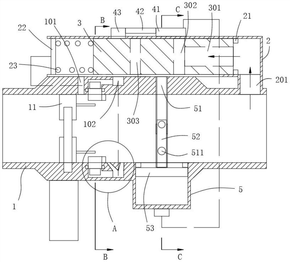
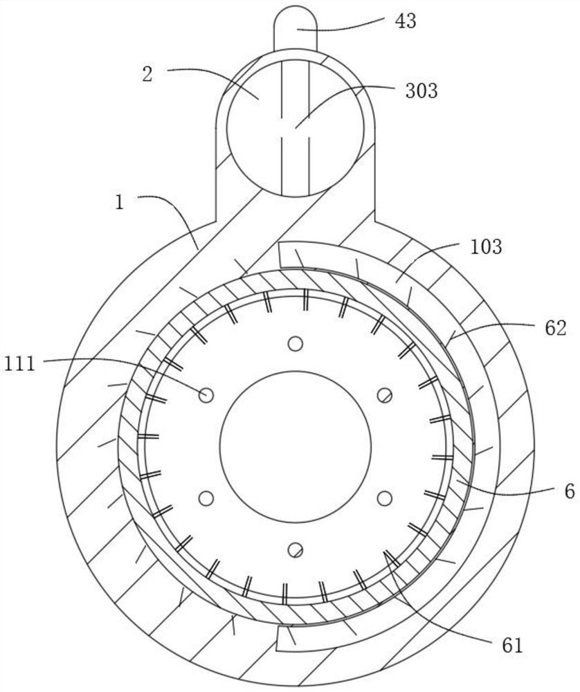
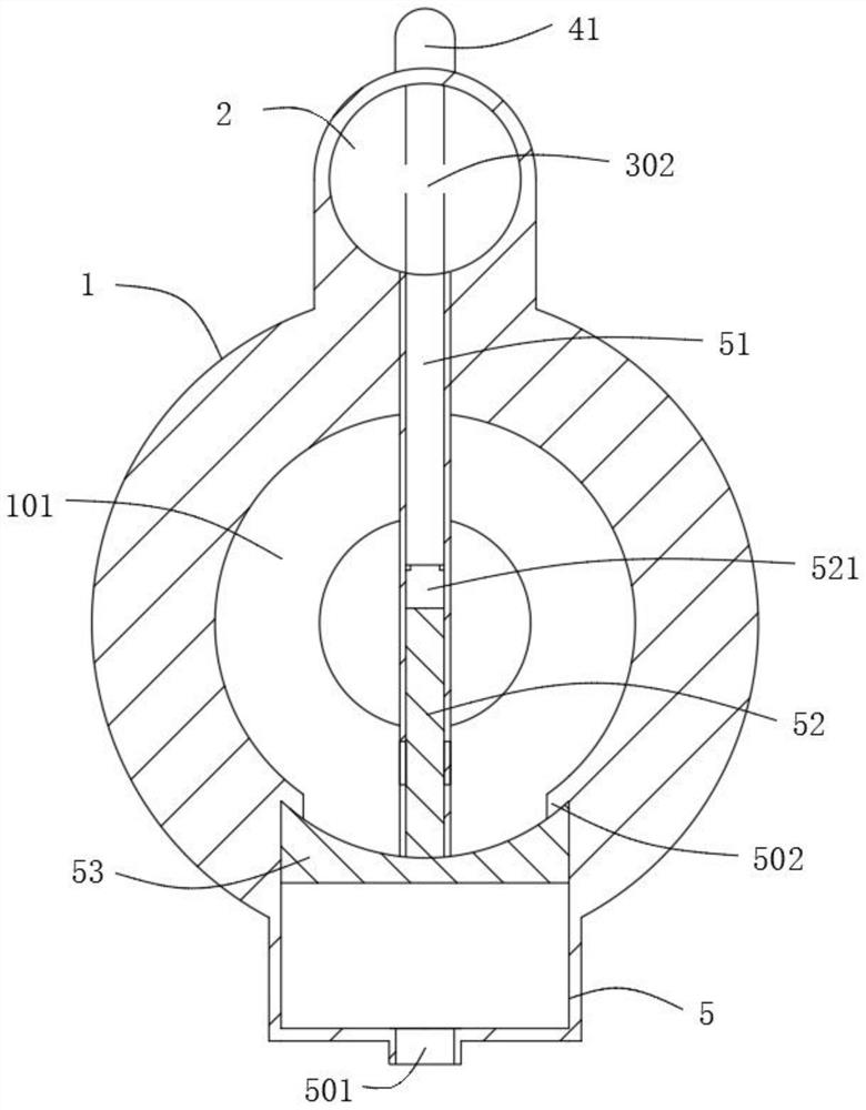
[0031] Example: such as Figure 1~6 As shown, the mechanical automatic control range constant pressure dredging valve includes a valve 11 installed in the delivery pipeline 1, and a pressure cylinder 2 is installed on the outer wall of the delivery pipeline 1. Moving movable plug 3, one end of pressure cylinder 2 communicates with conveying pipeline 1 through air inlet chamber 201, and air inlet chamber 201 is at least 30cm away from valve 11, an...


PUM


Abstract

The invention relates to the technical field of material conveying valves, in particular to a mechanical automatic controlled range constant pressure dredging valve. The dredging valve comprises a valve installed in a conveying pipeline, a pressure cylinder is installed on the outer wall of the conveying pipeline, a movable plug which is pressed to move in the axial direction is arranged in the pressure cylinder, one end of the pressure cylinder is communicated with the conveying pipeline through an air inlet cavity, and the distance between the air inlet cavity and the valve is at least 20 cm. According to the mechanical automatic controlled range constant pressure dredging valve, the pressure difference of the conveying pipeline is used for enabling the movable plug to act, the pressureat the far end of the pipeline is used for transmitting the dredging assembly, a capacity increasing component is used for increasing the capacity of the blocked space, a pressurizing component and astirring component are used for stirring and crushing the blocked position, and the blocked position is filled into the capacity increasing space; and dense materials at the blocked position are gradually loosened and can distribution from the valve, dredging can be completed without large external pressurization, the crushing effect of the blocked materials after dredging is good, and the subsequent pipe blocking probability is reduced.

Description

technical field [0001] The invention relates to the technical field of material conveying valves, in particular to a range constant pressure dredging valve with mechanical automatic control. Background technique [0002] During the material conveying process, especially at the front end of the valve, when the valve is closed, it is easy to accumulate material there. When the valve is opened again, due to the compression of the material, it will be blocked at the front end of the valve, resulting in blocked pipes. Most of the current solutions to the problem of blocked pipes are in the A high-pressure blow-assisted valve connected to the pipeline is installed on the material conveying pipeline. When the pipe is blocked, the device instantly fills a large amount of high-pressure gas into the conveying pipeline to blow away the blocked material and make the pipe unblocked. Both require an independent detection device to detect the phenomenon of material blockage and increase th...

Claims


Application Information

Patent Timeline
Patent Type & Authority Applications(China)
IPC IPC(8): F16L55/24F16L55/07B08B9/032B02C19/06
CPCB02C19/06B08B9/0325F16K27/00F16K37/0091F16L55/07F16L55/24
Inventor 王凤明
Owner SUZHOU BATAO INFORMATION TECH CO LTD
Why Eureka
Try Eureka