
Heat exchanger

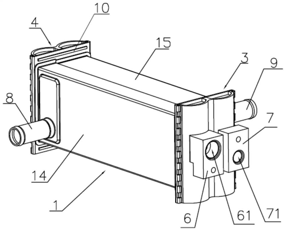
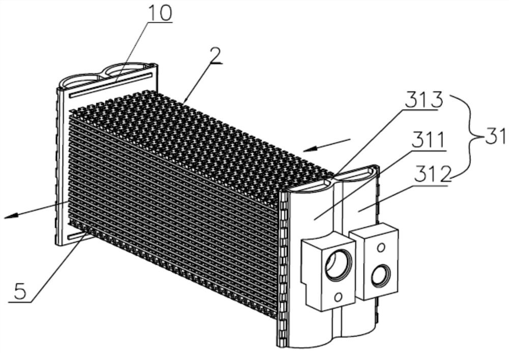
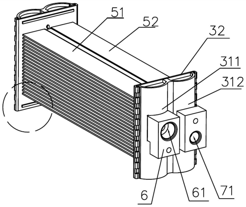
A heat exchanger and heat exchange tube technology, which is applied in the field of heat exchange, can solve problems such as affecting heat exchange effect and serial flow, and achieve the effect of reducing serial flow and improving heat exchange efficiency.

Inactive Publication Date: 2020-09-29
SANHUA HLDG GRP
View PDF8 Cites 0 Cited by
  • Summary
  • Abstract
  • Description
  • Claims
  • Application Information

AI Technical Summary

Problems solved by technology

However, after the fluid is introduced into the inner cavity of the heat exchanger, since there is a gap between the heat exchange tubes of each layer of heat exchange elements, the channels between the layers are connected, and the fluid flowing in each channel converges when flowing through the gap. Cause fluid flow and affect heat transfer effect

Method used


Image

  • Heat exchanger
  • Heat exchanger
  • Heat exchanger

Examples


Embodiment Construction

[0028] Reference will now be made in detail to the exemplary embodiments, examples of which are illustrated in the accompanying drawings. When the following description refers to the accompanying drawings, the same numerals in different drawings refer to the same or similar elements unless otherwise indicated. The implementations described in the following exemplary embodiments do not represent all implementations consistent with this application. Rather, they are merely examples of apparatuses and methods consistent with aspects of the present application as recited in the appended claims.

[0029] The terminology used in this application is for the purpose of describing particular embodiments only, and is not intended to limit the application. As used in this application and the appended claims, the singular forms "a", "the", and "the" are intended to include the plural forms as well, unless the context clearly dictates otherwise.

[0030] It should be understood that "fir...


PUM


Abstract

The invention relates to the field of heat exchange, in particular to a heat exchanger. The heat exchanger comprises a shell, a first current collecting piece, a second current collecting piece and heat exchange pieces; the shell comprises a first end and a second end, and the shell is provided with an inner cavity penetrating through the first end and the second end; the first current collectingpiece is connected with the first end, and the second current collecting piece is connected with the second end; the multiple heat exchange pieces are arranged in parallel at intervals, at least partsof the heat exchange pieces are located in the inner cavity of the shell, the inner cavity of the shell is divided into multiple first channels through the heat exchange pieces, and the first flow collecting piece communicates with the second flow collecting piece through the heat exchange pieces; and the heat exchange pieces comprise first heat exchange pipes, second heat exchange pipes and connecting parts connected between the first heat exchange pipes and the second heat exchange pipes. According to the heat exchanger, the problem that fluid flowing in different layers is converged when flowing through gaps due to layer-to-layer communication between the heat exchange pieces, and then the fluid series flow is caused is solved.

Description

technical field [0001] The present application relates to the field of heat exchange, in particular to a heat exchanger. Background technique [0002] The relevant heat exchanger arranges multi-layer heat exchange elements at intervals and in parallel in its inner cavity, so that its inner cavity is divided into multiple channels, and in order to increase the flow of refrigerant, each layer of heat exchange elements is composed of at least two rows of spaced and parallel arranged Composition of heat exchange tubes. However, after the fluid is introduced into the inner cavity of the heat exchanger, since there is a gap between the heat exchange tubes of each layer of heat exchange elements, the channels between the layers are connected, and the fluid flowing in each channel converges when flowing through the gap. Cause fluid flow, affect the heat transfer effect. Contents of the invention [0003] In view of the above problems existing in the prior art, the present applic...

Claims


Application Information

Patent Timeline
Patent Type & Authority Applications(China)
IPC IPC(8): F28D7/16F28F13/06
CPCF28D7/1615F28F13/06
Inventor 不公告发明人
Owner SANHUA HLDG GRP
Learn More