Eureka AIR delivers breakthrough ideas for toughest innovation challenges, trusted by R&D personnel around the world.

Visual lens

A lens and vision technology, applied in the field of vision lenses, can solve the problems of small supporting target surface, narrow working distance, low pixel, etc., and achieve the effect of wide working distance, small distortion and high pixel.

Pending Publication Date: 2020-09-29
DONGGUAN YUTONG OPTICAL TECH
View PDF0 Cites 3 Cited by
  • Summary
  • Abstract
  • Description
  • Claims
  • Application Information

AI Technical Summary

Problems solved by technology

However, the visual lenses in the prior art have low pixels, large distortion, small support target surface, and narrow working distance

Method used

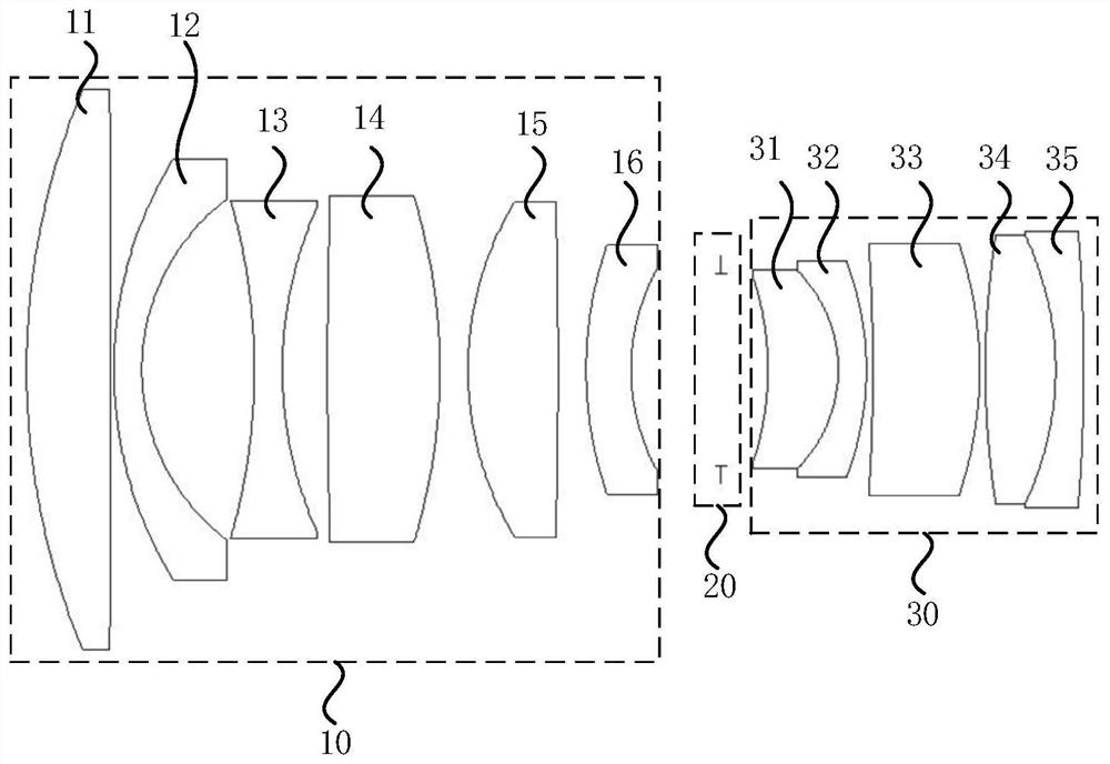
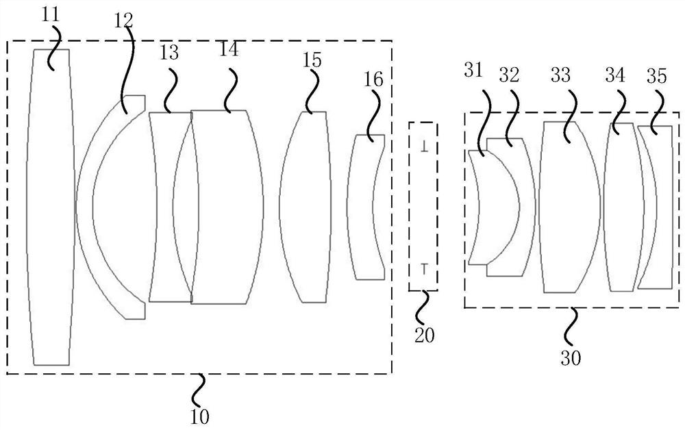
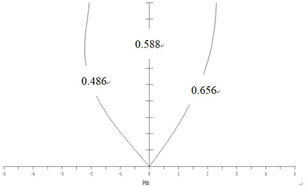

Image

  • Visual lens
  • Visual lens
  • Visual lens

Examples


Embodiment Construction

[0041] The present invention will be further described in detail below in conjunction with the accompanying drawings and embodiments. It should be understood that the specific embodiments described here are only used to explain the present invention, but not to limit the present invention. In addition, it should be noted that, for the convenience of description, only some structures related to the present invention are shown in the drawings but not all structures.

[0042] figure 1 is a structural schematic diagram of a vision lens provided by an embodiment of the present invention, as shown in figure 1 As shown, the visual lens provided by the embodiment of the present invention includes: a first lens group 10, a diaphragm 20 and a second lens group 30 arranged in sequence along the optical axis; The first lens 11 with positive refractive power, the second lens 12 with negative refractive power, the third lens 13 with negative refractive power, the fourth lens 14 with posit...


PUM


Abstract

The embodiment of the invention discloses a visual lens, which comprises a first lens group, a diaphragm and a second lens group which are sequentially arranged along an optical axis, wherein the first lens group comprises a first lens with positive focal power, a second lens with negative focal power, a third lens with negative focal power, a fourth lens with positive focal power, a fifth lens with positive focal power and a sixth lens with negative focal power which are sequentially arranged from an object side to an image side along an optical axis, and the second lens group comprises a seventh lens with negative focal power, an eighth lens with positive focal power, a ninth lens with positive focal power, a tenth lens with positive focal power and an eleventh lens with negative focal power which are sequentially arranged along the optical axis from the object side to the image side. The visual lens provided by the embodiment of the invention can meet the requirements of small occupied space, small distortion and wide working distance.

Description

technical field [0001] Embodiments of the present invention relate to the technical field of optical imaging, and in particular to a visual lens. Background technique [0002] With the increasing degree of industrial automation, the continuous development of machine vision systems has been driven. [0003] In the machine vision system, the imaging quality of the lens plays a vital role and directly affects the overall performance of the machine vision system. With the increasing application of machine vision in many fields such as electronic product manufacturing, food packaging, intelligent logistics, and medical diagnosis, the technical requirements of machine vision lenses are also getting higher and higher. Pixel advanced features. However, the visual lens in the prior art has low pixels, large distortion, small support target surface, and narrow working distance. Contents of the invention [0004] An embodiment of the present invention provides a visual lens to ach...

Claims


Application Information

Patent Timeline
Patent Type & Authority Applications(China)
IPC IPC(8): G02B15/17G02B15/14
CPCG02B15/17G02B15/1461
Inventor 张占军米士隆韩妮刘创标
Owner DONGGUAN YUTONG OPTICAL TECH
Why Eureka
Eureka Blog
Learn More