High-protection pouring bus duct

A busway and high protection technology, applied in the field of electric power, can solve the problems of low use efficiency of cast busbars, discounted busbar service life, troublesome use, etc., and achieve the effects of improving heat transfer efficiency, improving seismic performance and improving buffer performance.

Pending Publication Date: 2020-09-29
杰铭电气科技(镇江)有限公司
View PDF1 Cites 0 Cited by
  • Summary
  • Abstract
  • Description
  • Claims
  • Application Information

AI Technical Summary

Problems solved by technology

[0002] Bus bar refers to products made of high-conductivity copper and aluminum materials, used to transmit electric energy, and has the ability to collect and distribute electric power. It is the main conductor used to transmit electric energy in power stations or substations. The cast bus duct is made of high-performance insulating resin. , can be applied to various harsh and high-clean environments, and is widely used in various places such as shipbuilding, papermaking, power plants, substations, petrochemicals, iron and steel metallurgy, machinery and electronics, and large buildings. In the prior art, the authorized public number is CN207251136U The patent disclosed a cast bus duct, a cast bus duct, including a conductor, characterized in that: the conductor is potted in epoxy resin, the end of the conductor is supported by an insulating clip; the bus joint at the end of the c

Method used


Image

  • High-protection pouring bus duct
  • High-protection pouring bus duct
  • High-protection pouring bus duct

Examples


Embodiment Construction

[0028] The technical solutions in the embodiments of the present invention will be clearly and completely described below in conjunction with the accompanying drawings in the embodiments of the present invention. Obviously, the described embodiments are only a part of the embodiments of the present invention, rather than all the embodiments. Based on the embodiments of the present invention, all other embodiments obtained by those of ordinary skill in the art without creative work shall fall within the protection scope of the present invention.

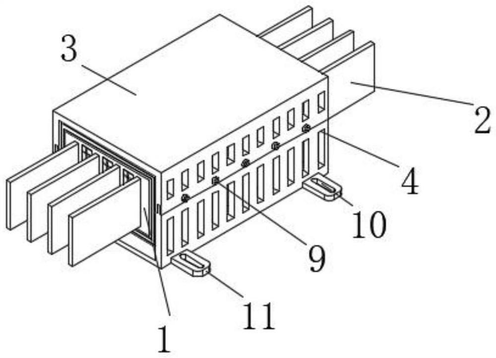
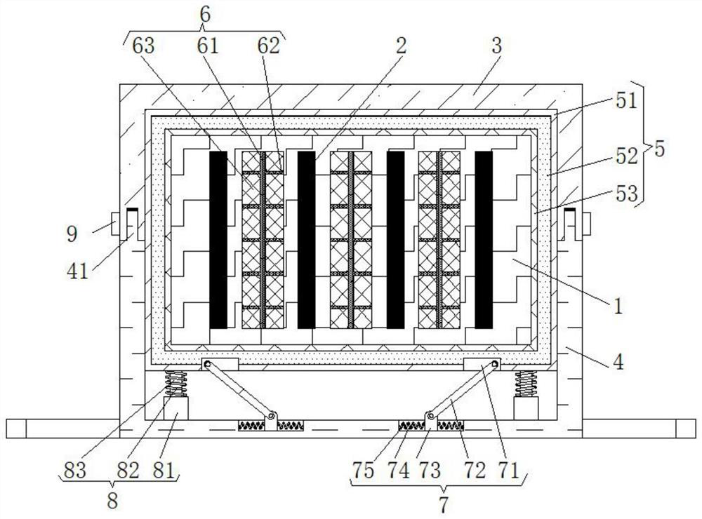
[0029] See Figure 1-3 , The present invention provides a technical solution: a high-protection pouring busway, including a busway 1, a lower shell 4, a heat dissipation component 6, a first shock-absorbing component 7 and a second shock-absorbing component 8;

[0030] Busway 1: Busbars 2 are arranged equidistantly inside, and evenly distributed cavities are arranged inside the busway 1, the cavity of busway 1 is located between adjacent b...


PUM


Abstract

The invention discloses a high-protection pouring bus duct which comprises a bus duct body, a lower shell, a heat dissipation assembly, first damping assemblies and second damping assemblies. Bus bares are arranged in the bus duct at equal intervals, cavities are evenly distributed in the bus duct, the cavities of the bus duct are located between the adjacent bus bars, and a protection plate is arranged on the outer surface of the bus duct. An upper shell is arranged at the upper end of the lower shell, and the outer surface of the protection plate is slidably connected with the inner wall surfaces of the upper shell and the lower shell; the heat dissipation assembly is arranged in the cavity of the bus duct; the first damping assemblies are arranged at the bottom end of the protection plate and the upper end of the bottom plate of the lower shell respectively; and the second damping assemblies are symmetrically arranged at the lower surface of the protection plate and the upper surface of the bottom plate of the lower shell. The high-protection pouring bus duct has the advantages that the high-protection pouring bus duct is extremely high in anti-vibration performance and good inheat dissipation performance, the aging rate can be decreased, the service life can be prolonged, flame-retardant and damp-proof effects can be realized, the practical performance can be improved, andthe high-protection pouring bus duct is convenient to use.

Description

Technical field [0001] The invention relates to the technical field of electric power, in particular to a high-protection pouring bus duct. Background technique [0002] Busbar refers to a product made of high-conductivity copper and aluminum materials, which is used to transmit electric energy, and has the ability to collect and distribute electric power. The main conductor for power station or substation transmission electric energy. The cast bus duct is made of high-performance insulating resin. It can be applied to a variety of harsh and high-clean environments, and is widely used in shipbuilding, papermaking, power plants, substations, petrochemicals, steel metallurgy, machinery and electronics, and large buildings. In the existing technology, the authorized public number is CN207251136U The patent discloses a pouring busway, a pouring busway, including a conductor, characterized in that: the conductor is potted in epoxy resin, the end of the conductor is supported by an ins...

Claims


Application Information

Patent Timeline
IPC IPC(8): H02G5/06H02G5/10F16F15/067
CPCF16F15/067H02G5/06H02G5/10
Inventor 杨军浦长银
Owner 杰铭电气科技(镇江)有限公司
Why Eureka
Try Eureka