Key ultraviolet sterilization system and working method

An ultraviolet germicidal lamp and button technology, which is used in sanitary equipment, water supply devices, buildings, etc. for toilets, and can solve the problems of photocatalyst dose consumption, affecting sterilization effect, and human body damage.

Inactive Publication Date: 2020-10-02
GUANGZHOU LEDIA LIGHTING CO LTD
View PDF9 Cites 3 Cited by
  • Summary
  • Abstract
  • Description
  • Claims
  • Application Information

AI Technical Summary

Problems solved by technology

Some elevator buttons will also add a photocatalyst to improve the sterilization effect, but the photocatalyst is directly coated on the surface of the button. As time goes by, the dose of the photocatalyst will be consumed, which will affect the sterilization effect.
[0005] The button of this invention, by setting the germicidal lamp in the button, can sterilize by reflecting the ultraviolet rays to the transparent nameplate through the reflector, but in this case, it can only sterilize the local area that can be reflected by the reflector during sterilization. Not all areas of the button can be illuminated
[0006] In addition, ultraviolet light is harmful to the human body. If ultraviolet sterilization is carried out when there are people, although the sterilization of the keys is achieved, it will cause harm to the human body. In the actual application process, the current keys generally require direct contact with the human body. To achieve its function, therefore, it is very necessary to solve the technical problem of not sterilizing when the human body is pressed, but sterilizing after the pressing is completed

Method used


Image

  • Key ultraviolet sterilization system and working method
  • Key ultraviolet sterilization system and working method
  • Key ultraviolet sterilization system and working method

Examples


Embodiment Construction

[0035] The present invention will be described in further detail below in conjunction with the accompanying drawings and specific embodiments.

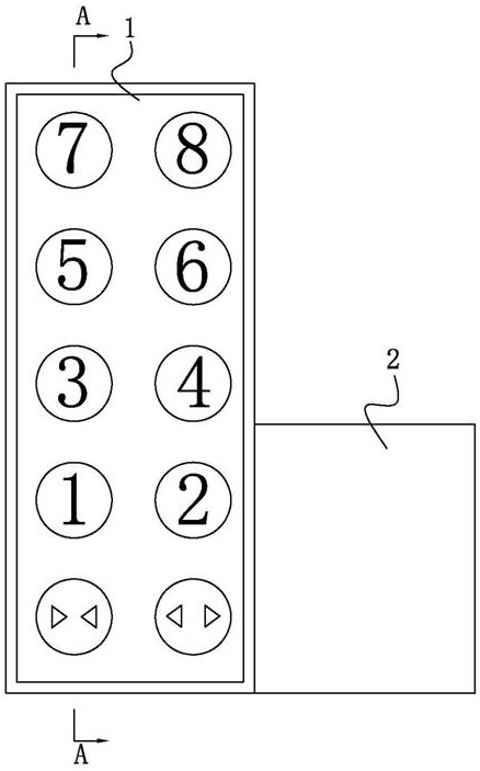
[0036] Such as figure 1 As shown, the button ultraviolet sterilization system includes a button sterilization device 1 and a control device 2 .

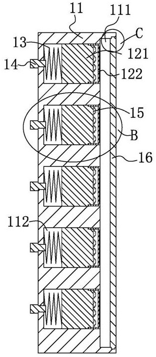
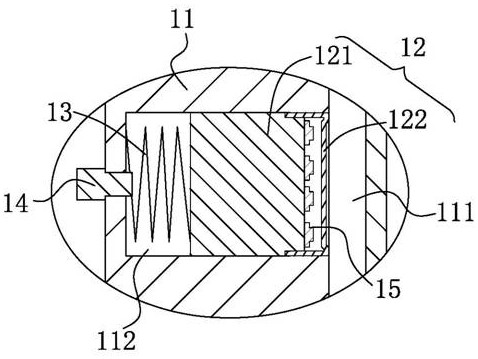
[0037] Such as figure 2 with image 3 As shown, the key sterilization device 1 includes a key base 11 , a key 12 , a return spring 13 and a distance sensor 14 . The front end of the key base 11 is provided with a cavity 111, and the key base is provided with an accommodating cavity 112 equal to the number of keys, and the accommodating cavity extends backward from the cavity 111; a key 12 is provided sliding in the accommodating cavity 112, The key 12 includes a key body 121 and a transparent cover 122 arranged on the key body. The transparent cover 122 is a silicone transparent cover. An ultraviolet germicidal lamp 15 with a transparent cover, the ultraviolet germicidal lamp is a UVC g...


PUM


Abstract

The invention discloses a key ultraviolet sterilization system and a working method. The key ultraviolet sterilization system comprises a key sterilization device and a control device, wherein the keysterilization device comprises a key seat, a key, a reset spring, a distance sensor and a light shielding plate; the control device comprises a sterilization seat, a sliding block, a driving device,a linkage mechanism and a controller; a sliding groove is formed in a side surface of the sliding block and comprises a first sliding groove, a buffer groove, a second sliding groove and a reset groove; an elastic sheet is arranged at the joint of the first sliding groove and the buffer groove on the sliding block; the middle of the elastic sheet protrudes towards the rear end of the sliding blockto form an arc; and the linkage mechanism comprises a driving rod, a fixing pin, a fixing rod, a connecting pin, a spring, a fixing block and a trigger switch, and further comprises a human body sensor. According to the working method, when the key is pressed by a hand, an ultraviolet sterilization lamp does not work, otherwise, the ultraviolet sterilization lamp works, and light shielding is carried out by utilizing the light shielding plate. According to the key ultraviolet sterilization system and the working method, the key can be pressed, the key can be sterilized after pressing is completed, and no harm is caused to a human body.

Description

technical field [0001] The invention relates to the technical field of button sterilization, in particular to a button ultraviolet sterilization system and working method. Background technique [0002] With the continuous acceleration of the pace of life, in order to move people in buildings safely, quickly, conveniently and effectively, elevators have been widely used in public places such as supermarkets, large shopping malls, hospitals and various entertainment venues. , fast, time-saving and labor-saving important means of delivery. With the rapid development and growth of the elevator manufacturing industry, the technology of elevator supporting products is also constantly updating and changing, and the elevator button is one of them. [0003] The elevator button is an important part to control the operation of the elevator. It is also the part that people touch the most. Has quietly become a potential source of bacterial contamination. Therefore, it is necessary to ...

Claims


Application Information

Patent Timeline
Patent Type & Authority Applications(China)
IPC IPC(8): A61L2/10A61L2/24A61L2/26
CPCA61L2/10A61L2/24A61L2/26A61L2202/14
Inventor 黄灿明朱从文吕鹤男吴芳明杨艳春刘玉生
Owner GUANGZHOU LEDIA LIGHTING CO LTD
Why Eureka
Try Eureka