Industrial dust removal equipment
A kind of dust removal equipment, industrial technology, applied in lighting and heating equipment, dispersed particle filtration, application, etc., can solve the problem of inability to adjust the horizontal tilt angle of dust removal, and achieve stable production capacity, large economic benefits, and maintain working conditions and efficiency.
- Summary
- Abstract
- Description
- Claims
- Application Information
AI Technical Summary
Problems solved by technology
Method used
Image

Examples
specific Embodiment approach 1
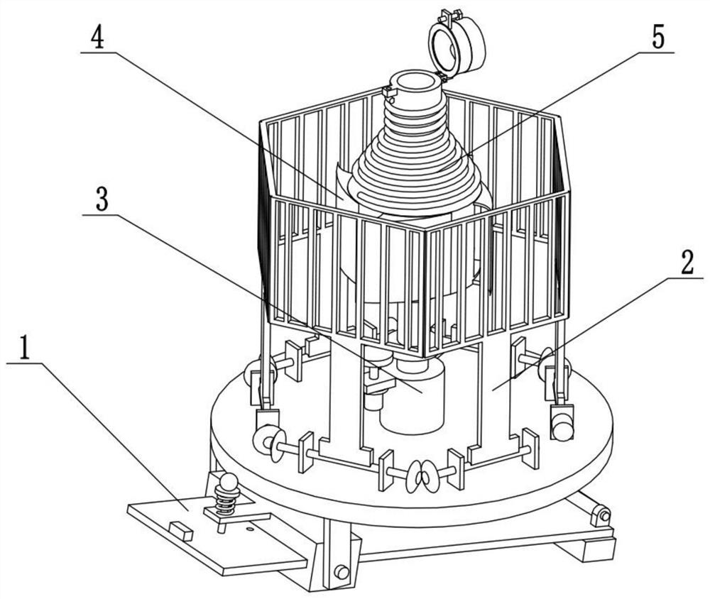
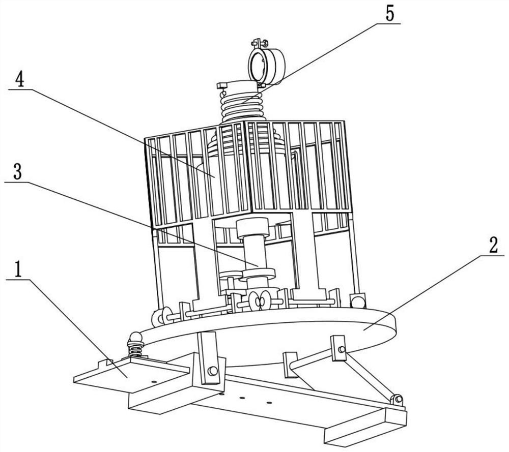
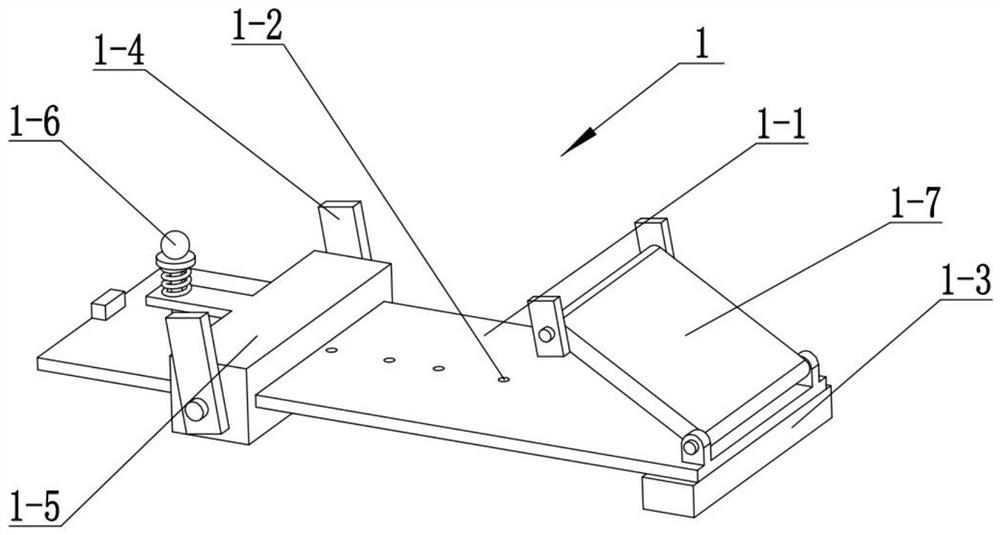
[0029] Combine below figure 1 , 2 , 3, 4, 5, 6, 7, and 8 illustrate this embodiment. The present invention relates to the technical field of industrial dust removal, more specifically, an industrial dust removal equipment, including an angle tilt mechanism 1, a rotation protection mechanism 2, and a rotation driving mechanism 3. The spiral air guide mechanism 4 and the dust removal and cooling mechanism 5, the angle tilt mechanism 1 is fixedly connected to the bottom of the rotation protection mechanism 2, the rotation drive mechanism 3 is fixedly connected to the rotation protection mechanism 2, and the spiral air guide mechanism 4 is fixedly connected On the rotary drive mechanism 3, the dust removal and cooling mechanism 5 is fixedly connected to the spiral air guide mechanism 4. The angle tilt mechanism 1 includes a stable slide plate 1-1, an angle hole 1-2, a horizontal pad 1-3, and a suspension 1-4, inclined slideways 1-5, fixed pins 1-6 and slanting braces 1-7, the bot...
specific Embodiment approach 2
[0031] Combine below figure 1 , 2, 3, 4, 5, 6, 7, and 8 illustrate this embodiment, and this embodiment will further explain Embodiment 1. The described rotation protection mechanism 2 includes a tilting chassis 2-1, an opening and closing shaft 2-2, a bevel gear 2-3, the opening and closing motor 2-4 and the safety guardrail 2-5, the six safety guardrails 2-5 are respectively fixedly connected to the six opening and closing shafts 2-2, and the six opening and closing shafts 2-2 are all rotatably connected to the On the inclined chassis 2-1, the two suspensions 1-4 are fixedly connected to the bottom of the inclined chassis 2-1, the top of the slanting brace plate 1-7 is connected to the bottom of the inclined chassis 2-1 in rotation, and the two adjacent openings The joint shafts 2-2 are meshed and driven by bevel gears 2-3, and one of the opening and closing shafts 2-2 is driven to rotate by the output shaft of the opening and closing motor 2-4, thereby driving the six open...
specific Embodiment approach 3
[0033] Combine below figure 1 , 2 , 3, 4, 5, 6, 7, and 8 illustrate this embodiment, and this embodiment will further illustrate Embodiment 2. The described rotary drive mechanism 3 includes a base 3-1, a rotating shaft 3-2, a ring rack 3-3, the rotating motor 3-4 and the driving gear 3-5, the driving gear 3-5 is fixedly connected to the output shaft of the rotating motor 3-4, the output shaft of the rotating motor is fixedly connected to the base 3-1, and the base 3-1 Fixedly connected to the middle part of the inclined chassis 2-1, the bottom end of the rotating shaft 3-2 is connected to the base 3-1 in rotation, the ring rack 3-3 is fixedly connected to the rotating shaft 3-2, and the ring rack 3-3 is connected to the drive The gear 3-5 meshes and drives, and the spiral air guide mechanism 4 is fixedly connected to the top of the rotating shaft 3-2; the rotating motor 3-4 drives the driving gear 3-5 to rotate, and the driving gear 3-5 drives the ring rack 3-3 and the rotat...
PUM
 Abstract
Description
Claims
Application Information
 - R&D Engineer
- R&D Manager
- IP Professional
- Industry Leading Data Capabilities
- Powerful AI technology
- Patent DNA Extraction
Browse by: Latest US Patents, China's latest patents, Technical Efficacy Thesaurus, Application Domain, Technology Topic.
© 2024 PatSnap. All rights reserved.Legal|Privacy policy|Modern Slavery Act Transparency Statement|Sitemap