
Concrete wall rapid pouring equipment

A concrete wall and fast technology, applied in the field of building pouring, can solve the problems of low efficiency and high labor intensity, and achieve the effects of reducing human labor, speeding up pouring speed, and improving building construction efficiency.

Inactive Publication Date: 2020-10-02
缙云松弛自动化科技有限公司
View PDF0 Cites 3 Cited by
  • Summary
  • Abstract
  • Description
  • Claims
  • Application Information

AI Technical Summary

Problems solved by technology

[0002] At present, with the development of society and the continuous improvement of construction technology, the walls in the building do not need to be directly built on the building, it can be poured, and then the wall is fixed to the building, solidification saves construction time, and the concrete pouring will be well mixed The concrete material is poured into the warehouse, closed, and tamped. The pouring requires continuous, uniform and prevents segregation of the concrete. However, the existing pouring needs to be stirred to generate concrete, and then poured into the model. Concrete unloading and tamping is inefficient and labor-intensive

Method used

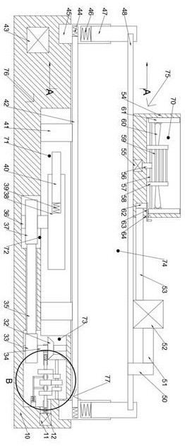
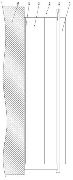
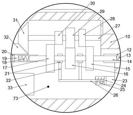

Image

  • Concrete wall rapid pouring equipment
  • Concrete wall rapid pouring equipment
  • Concrete wall rapid pouring equipment

Examples


Embodiment Construction

[0013] All features disclosed in this specification, or steps in all methods or processes disclosed, can be combined in any way, except for mutually exclusive features and or steps.

[0014] Combine below Figure 1-3 The present invention is described in detail, and for convenience of description, the orientations mentioned below are now stipulated as follows: figure 1 The up, down, left, right, front and back directions of the projection relationship itself are the same.

[0015] A rapid concrete wall pouring equipment of the device of the present invention comprises a machine body 10, two front and back symmetrical side plates 49 are fixed on the upper side of the machine body 10, and two left and right symmetrical fixing columns are fixed on the upper side of the machine body 10 45, a lifting rod 47 is slidably connected to each of the fixed columns 45, a lifting spring 46 is connected between the lifting rod 47 and the fixed column 45, and an upper cover plate 48 is slida...


PUM


Abstract

The invention discloses concrete wall rapid pouring equipment. The concrete wall rapid pouring equipment comprises a machine body, two side plates which are in front and back symmetry are fixedly mounted on the upper side face of the machine body, two fixing columns in bilateral symmetry are fixedly mounted on the upper side of the machine body, a lifting rod is in sliding connection into each fixing column, a lifting spring is connected between each lifting rod and the corresponding fixing column, an upper cover plate is in sliding connection between the lifting rods, the upper side face ofthe upper cover plate is fixedly provided with a stirring body and a high-pressure pump, a stirring cavity is formed in the stirring body, a vibration cavity is formed in the upper side of the machinebody, a belt wheel cavity is formed in the lower side of the vibration cavity, a speed adjusting cavity is formed in the right side of the vibration cavity, a solidifying cavity is formed between theupper cover plate and the machine body, a stirring device for stirring concrete is arranged in the stirring cavity, a vibrating device for vibrating the concrete is arranged in the vibration cavity,a speed adjusting device for speed adjusting is arranged in the speed adjusting cavity, according to the equipment, stirring forming of the concrete can be automatically finished, rapid filling is carried out, concrete is flatly paved in a sense manner, manpower can be reduced, the pouring speed is quickened, and the building construction efficiency is improved.

Description

technical field [0001] The invention relates to the related fields of building pouring, in particular to a rapid pouring equipment for concrete walls. Background technique [0002] At present, with the development of society and the continuous improvement of construction technology, the walls in the building do not need to be directly built on the building, it can be poured, and then the wall is fixed to the building, solidification saves construction time, and the concrete pouring will be well mixed The concrete material is poured into the warehouse, closed, and tamped. The pouring requires continuous, uniform and prevents segregation of the concrete. However, the existing pouring needs to be stirred to generate concrete, and then poured into the model. Concrete unloading and tamping is inefficient and labor-intensive. Contents of the invention [0003] Aiming at the deficiencies of the above-mentioned technologies, the present invention proposes a rapid pouring equipmen...

Claims


Application Information

Patent Timeline
IPC IPC(8): B28C5/16B28C7/16B28B1/087
CPCB28B1/087B28C5/16B28C7/162
Inventor 曾泽坤
Owner 缙云松弛自动化科技有限公司
Learn More