Sprue structure used for injection mold and injection mold

An injection mold and gate technology, applied in the field of mold injection technology, can solve the problems of inability to fill the molding cavity of molten plastic, poor plastic fluidity, flow marks of molded products, etc. The effect of reducing the generation of streaks

Pending Publication Date: 2020-10-02
MANSHENG PACKAGING SHANGHAI
View PDF0 Cites 2 Cited by
  • Summary
  • Abstract
  • Description
  • Claims
  • Application Information

AI Technical Summary

Problems solved by technology

However, for some molds with long runners, the fluidity of the plastic will become poor, which will make it impossible for the molten plastic to fill the inside of the molding cavity stably, resulting in flow marks, bubbles, joint lines, and ripples in the molded product. and uneven shrinkage, especially for products with transparent materials, the yield rate is low

Method used


Image

  • Sprue structure used for injection mold and injection mold
  • Sprue structure used for injection mold and injection mold
  • Sprue structure used for injection mold and injection mold

Examples


Embodiment 1

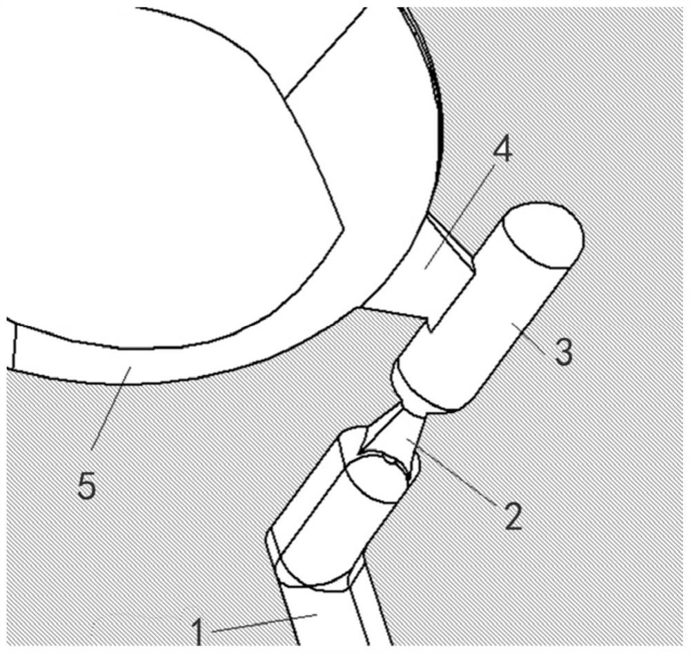
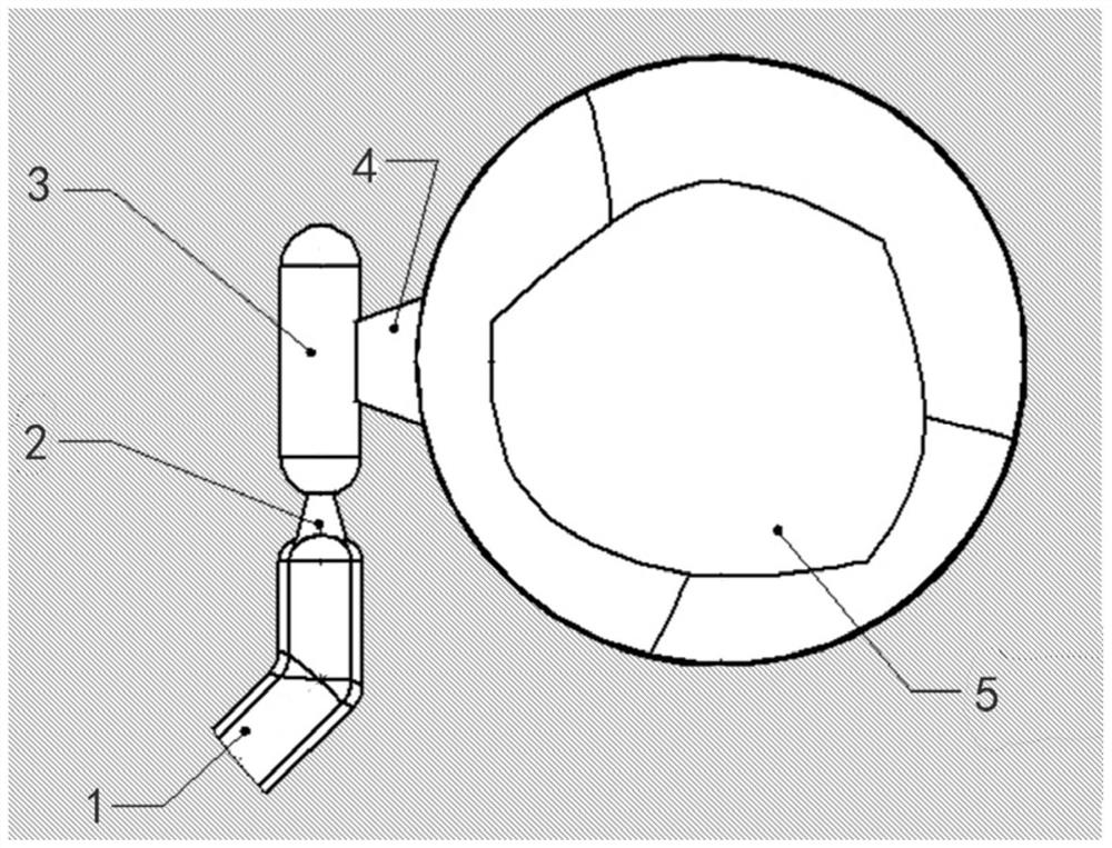
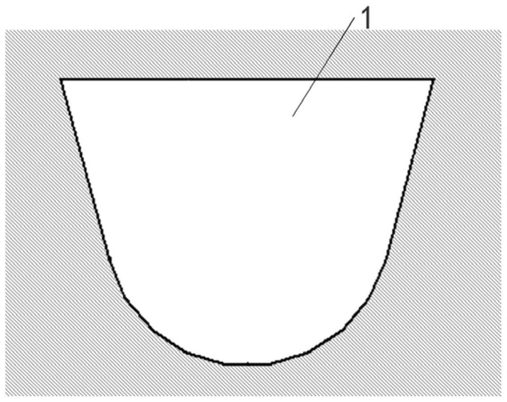
[0028] Such as figure 1 with figure 2 As shown, this embodiment provides a gate structure for an injection mold, which includes a primary runner 1, a restricted gate 2, a secondary runner 3, and an unrestricted gate 4. One end of the primary runner 1 is a pouring port, the other end is connected to the inlet of the restriction gate 2, and the outlet of the restriction gate 2 is connected to the secondary runner 3. The secondary runner 3 is connected to the molding cavity 5 through an unrestricted outlet. Specifically, the inlet of the unrestricted gate 4 is connected to the center of the side wall of the secondary runner 3 and the outlet is connected to the molding cavity 5.

[0029] The restriction gate 2 is a cone, the outlet of the restriction gate 2 is arranged at the top end of the cone, and the inlet of the restriction gate 2 is arranged at the bottom end of the cone. The cross-sectional area of ​​the inlet of the gate 2 is restricted to be larger than the cross-sectional ...

Embodiment 2

[0033] Such as Figure 5 As shown, this embodiment provides an injection mold, which includes four gate structures disclosed in the first embodiment. The product geometry of the injection mold is irregular wall thickness, the outer diameter is round, and 100% PMMA is used. Therefore, the product has requirements for transparency, high quality requirements for appearance, and no appearance problems such as flow marks, bubbles and cold materials.

[0034] In this embodiment, the four molding cavities are arranged in a row and the four gate structures are arranged in a cross shape to achieve overall flow channel balance. The pouring ports of the primary runners of all gate structures are connected and located in the center of the mold, so that the melt can evenly enter each gate structure through a pouring port, so that the plastic melt can be quickly and evenly filled into the molding cavity. Get qualified products.


PUM


Abstract

The invention relates to a sprue structure used for an injection mold and the injection mold. The sprue structure comprises a first-stage runner, a limiting sprue, a second-stage runner and a non-limiting sprue. A pouring port is arranged at one end of the first-stage runner, and an inlet connected with the limiting sprue is connected to the other end of the first-stage runner. An outlet of the limiting sprue is connected with the second-stage runner. An inlet of the non-limiting sprue is connected with the second-stage runner, and an outlet of the non-limiting sprue is connected with a forming cavity. The sectional area of the first-stage runner is larger than that of the second-stage runner, the sectional area of the inlet of the limiting sprue is larger than the sectional area of the outlet, and the sectional area of the inlet of the non-limiting sprue is smaller than that of the outlet. Compared with the prior art, plastic melt is subjected to acceleration and friction through thelimiting sprue, the temperature of the melt is increased, the ideal flowing state is achieved, the second-stage runner is rapidly full, and meanwhile the function of preventing the melt from flowing back is achieved; the melt in the second-stage runner is guided by the non-limiting sprue to fill the forming cavity, the phenomena of plastic eddies, turbulence and the like are not prone to being generated, and the forming quality of a final injection molded product is effectively improved.

Description

Technical field [0001] The invention relates to the field of mold injection technology, in particular to a gate structure for an injection mold and an injection mold. Background technique [0002] The gate is the part that connects the runner and the molding cavity in the injection mold. The function of the gate is to make the molten plastic from the runner enter the molding cavity at the fastest speed. When the molding cavity is full, the gate can be quickly cooled and sealed to prevent the uncooled plastic in the molding cavity from flowing back. The structure and location of the gate will directly affect whether the melt can be intact and high-quality injection molding. [0003] The existing gate is generally a short groove with a small cross section. Under normal circumstances, when molten plastic flows into the runner, the place where the molten material is close to the mold surface will first drop heat and solidify to form a solidified layer. When the molten material flows ...

Claims


Application Information

Patent Timeline
IPC IPC(8): B29C45/27
CPCB29C45/2701B29C45/2708B29C45/2725
Inventor 丁丹辉陈宏
Owner MANSHENG PACKAGING SHANGHAI
Why Eureka
Try Eureka