Eureka AIR delivers breakthrough ideas for toughest innovation challenges, trusted by R&D personnel around the world.

Rail transit turnout busbar transition piece and contact line clamping device

A rail transit and contact wire clip technology, applied in the field of rail transit, can solve the problems of large amount of suspension parts, poor adaptation of existing devices, and difficult to control installation accuracy, and achieve the effect of small bending radius, reduced consumption, and high consistency.

Pending Publication Date: 2020-10-02
CHINA RAILWAY HIGH SPEED ELECTRIFICATION EQUIP CORP LTD
View PDF0 Cites 0 Cited by
  • Summary
  • Abstract
  • Description
  • Claims
  • Application Information

AI Technical Summary

Problems solved by technology

[0003] Design a turnout transition and contact line clamping device to solve the problems of poor adaptability of existing devices, large amount of suspension parts and difficult control of installation accuracy. The technical solution adopted by the present invention is:

Method used


Image

  • Rail transit turnout busbar transition piece and contact line clamping device
  • Rail transit turnout busbar transition piece and contact line clamping device
  • Rail transit turnout busbar transition piece and contact line clamping device

Examples


Embodiment Construction

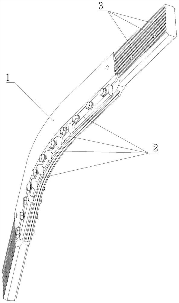
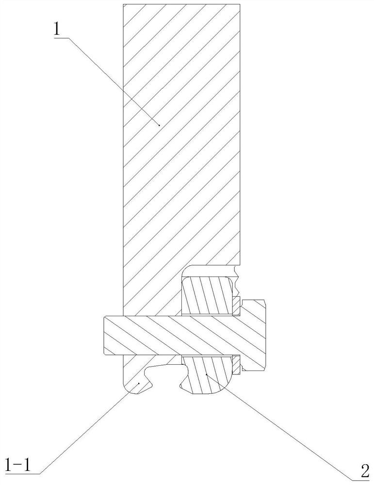
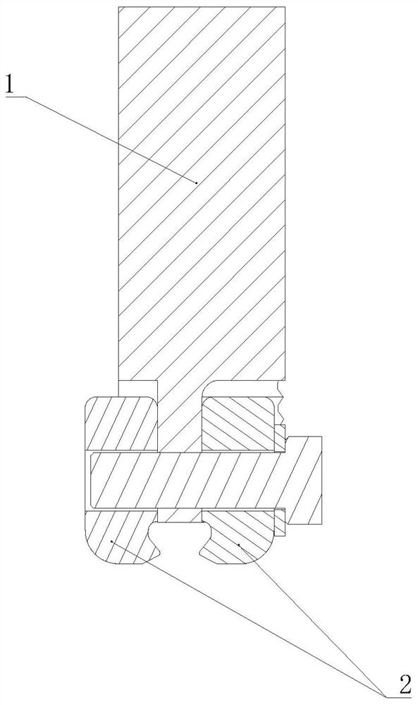
[0031] Such as figure 1 The busbar transition piece shown is used at the rail transit turnout. Since the turnout guides the train to change its route, the contact line here needs to follow the vehicle to change direction. The transition piece is used to change the direction of the contact line. The transition piece Including the transition piece body 1, the transition piece body 1 is bent along the length direction, that is, the bending direction of the transition piece body 1 is consistent with the branch flow direction of the switch, and a splint 2 is arranged on the lower edge of the transition piece body 1, and the contact line is clamped by the splint 2, The contact line is fixed at the bend of the turnout instead of the busbar; installation holes 3 are provided at both ends of the transition piece body 1, and the busbar is fixed on both ends of the transition piece body 1 through the installation holes 3.

[0032] figure 2 The clamping plate 2 shown is only provided on...


PUM


Abstract

The invention discloses a rail transit turnout busbar transition piece and a contact line clamping device. The transition piece comprises a transition piece body, the transition piece body is bent inthe length direction, and a clamping plate capable of clamping a contact line is arranged on the lower edge of the transition piece body. The structure for applying the transition piece to the contactline clamping device comprises a pair of transition piece bodies, wherein each transition piece body is bent along the length direction, the transition piece further comprises an anchoring plate connected with a positioning device, the pair of transition piece bodies are fixed on the anchoring plate to form an X shape, bus bars are arranged at the two ends of each transition piece body, and the clamping plate capable of clamping the contact line is arranged at the lower edge of each transition piece body; the transition piece is used for replacing a busbar so that the problem that the busbaris difficult to process due to an overlarge bending angle is avoided; the device is of an integrated hyperbolic structure, and the number of positioning and hanging parts and the number of center anchoring devices are reduced. The device is of an integrated structure, and the two contact lines can be consistent in height.

Description

technical field [0001] The invention relates to the field of rail transit, in particular to a contact line clamping device and a transition piece at a turnout. Background technique [0002] The existing rigid suspension system usually uses double mechanical pre-bending busbars for power supply at the diamond-shaped turnout. This method has the following three disadvantages: 1. The minimum mechanical pre-bending radius of the busbar is relatively large, and it cannot be used at small angles. The pull-out value of the contact line is guaranteed at the diamond-shaped turnout, and the scope of application is narrow; 2. The installation of the existing double busbar requires two sets of positioning suspension devices, and two sets of central anchoring devices are required, and the amount of suspension parts is large; 3. The installation is completed Finally, it is necessary to adjust the guide height of the two mechanically pre-bent busbars separately, and the construction accura...

Claims


Application Information

Patent Timeline
Patent Type & Authority Applications(China)
IPC IPC(8): B60M1/30H01R25/14
CPCB60M1/30H01R25/14
Inventor 邓相龙林建陈晓丹刘娟王正冯勇李逢源邢甲第赵金凤李晓军焦春晓王鹏勃刘学良杜宝峰
Owner CHINA RAILWAY HIGH SPEED ELECTRIFICATION EQUIP CORP LTD
Why Eureka
Eureka Blog
Learn More