Prefabricated stand column in-plant overturning method

The technology of a column and the other side is applied in the field of inversion of the prefabricated column factory, which can solve the problems of difficult column inversion, collapse of the column, heavy column weight, etc., and achieves the effects of high practical value, convenient setting, and simple construction and operation.

Inactive Publication Date: 2020-10-02
SHANGHAI NO 4 CONSTR
View PDF4 Cites 1 Cited by
  • Summary
  • Abstract
  • Description
  • Claims
  • Application Information

AI Technical Summary

Problems solved by technology

However, when the column is transported, due to the high height of the column, it cannot meet the conditions of road transportation. The column must be laid down and transported horizontally, which leads to the need for the column to be turned over once in the factory, from the vertical position to the horizontal position. state
[0003] Due to the heavy weight of the column and the protection of the finished concrete product from damage during the overturning process, the overturning operation of the column is difficult. Therefore, it is necessary to design a method and device for overturning the column to ensure that the overturning of the column components is safe and reliable. protect the concrete

Method used


Image

  • Prefabricated stand column in-plant overturning method
  • Prefabricated stand column in-plant overturning method
  • Prefabricated stand column in-plant overturning method

Examples


Embodiment Construction

[0033] The present invention will be described in detail below in conjunction with specific embodiments. The following examples will help those skilled in the art to further understand the present invention, but do not limit the present invention in any form. It should be noted that those skilled in the art can make several modifications and improvements without departing from the concept of the present invention. These all belong to the protection scope of the present invention.

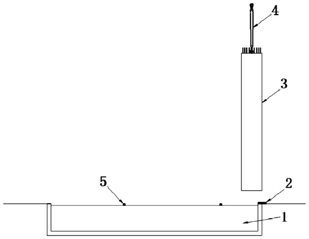
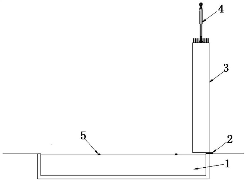
[0034] Referring to 1-6, it is a schematic diagram of the steps of a method for inverting a prefabricated column in a factory according to a preferred embodiment of the present invention, including the following steps:

[0035] S1: Set the flip area:

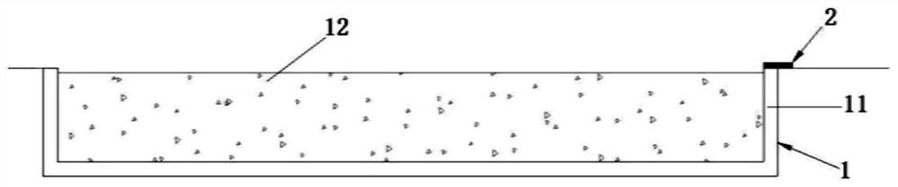
[0036] refer to figure 1 As shown, the overturning area includes a foundation pit 1, and the foundation pit 1 is surrounded by four side walls 11. The side walls 11 can support the prefabricated columns 3, and the inside of the foundation pit 1 is ...


PUM

PropertyMeasurementUnit
depthaaaaaaaaaa
thicknessaaaaaaaaaa

Abstract

The invention provides a prefabricated stand column in-plant overturning method. The method comprises the steps that an overturning area is arranged, wherein the overturning area comprises a foundation pit, the foundation pit is defined by side walls on the four sides, the side walls can support a prefabricated stand column, and the interior of the foundation pit is filled with sandy soil; the prefabricated stand column is overturned to a horizontal state from a vertical state, wherein the prefabricated stand column is vertically hoisted and moved to the position above one side wall of the foundation pit, and one side of the bottom of the prefabricated stand column is aligned with the side wall; the prefabricated stand column is lowered, one side of the bottom of the prefabricated stand column is supported on the side wall, and the other side of the bottom of the prefabricated stand column is suspended above the sandy soil; the prefabricated stand column continues to be lowered, the bottom of the prefabricated stand column overturns towards the interior of the foundation pit due to single-side stress, and the other side of the bottom of the prefabricated stand column is located inthe sandy soil; and under the traction of a hoisting device, the prefabricated stand column continues to be overturned till the prefabricated stand column completely lies in the foundation pit, and overturning of the prefabricated stand column from the vertical state to the horizontal state is completed. According to the prefabricated stand column in-plant overturning method, the overturning areais simple in component and easy and convenient to operate, and the effect of protecting the appearance of the prefabricated stand column is achieved.

Description

technical field [0001] The invention relates to the construction field of prefabricated columns in the construction of prefabricated bridges, in particular to a method for inverting prefabricated columns in a factory. Background technique [0002] When the prefabricated components of pier columns are produced in the factory, in order to facilitate the production of steel cages and the installation of formwork, horizontal cages are generally used to enter the mold. The rear column rests vertically on the pouring pedestal. However, when the column is transported, due to the high height of the column, it cannot meet the conditions of road transportation. The column must be laid down and transported horizontally, resulting in the column needing to be turned over once in the factory, from the vertical position to the horizontal position. state. [0003] Due to the heavy weight of the column and the protection of the finished concrete product from damage during the overturning p...

Claims


Application Information

Patent Timeline
Patent Type & Authority Applications(China)
IPC IPC(8): B66C13/08B66C1/12B66C1/18B28B17/00
CPCB28B17/00B66C1/12B66C1/18B66C13/08
Inventor 郑晏华李申杰干华铭周君李晨辉姚艳曹佳雯孙俊张剑宇董少白王冬张锡霖王灏
Owner SHANGHAI NO 4 CONSTR
Why Eureka
Try Eureka