Rear-stage pump control system and control method for vacuum system

A technology of a vacuum system and a control method, applied in the field of vacuum systems, can solve problems such as unfavorable integration, large equipment footprint, and need for additional power supply, so as to ensure service life and work stability, reduce equipment footprint, and reduce circuits. The effect of layout difficulty

Active Publication Date: 2020-10-02
AUTOBIO LABTEC INSTR CO LTD
View PDF9 Cites 2 Cited by
  • Summary
  • Abstract
  • Description
  • Claims
  • Application Information

AI Technical Summary

Problems solved by technology

For this reason, in daily matching, the following two combinations are often used: 1. A backstage mechanical pump with a higher pumping speed (such as a pumping speed of 1.5~2.0L / s) and a high pumping speed (such as a pumping speed of 220~ 280 L / s), the overall pumping speed of this combination is relatively fast, and can quickly reach the required vacuum degree, but because the pumping speed of the front-stage mechanical pump is proportional to the volume, its volume is large and requires Additional power supply is not conducive to integration, and the entire equipment occupies a large area; 2. The backstage mechanical pump with low pumping speed (such as pumping speed 0.28-0.45L / s) and low pumping speed (such as pumping speed 60-85L / s) ) composed of the back-stage molecular pump, which is characterized by the small size of the front-stage mechanical pump, which is conducive to integration, but because the overall pumping speed is low, the overall pumping speed is slow, and it takes a long time to make the vacuum The vacuum degree in the chamber reaches the required value
[0003] Due to the structural characteristics and limitations of the pumping speed ratio of the above-mentioned molecular pumps and mechanical pumps, it is difficult to take into account the volume and vacuuming speed when selecting a vacuum pump combination, which does not meet the user's needs for high vacuuming speed, small volume, and high integration.

Method used


Image

  • Rear-stage pump control system and control method for vacuum system
  • Rear-stage pump control system and control method for vacuum system
  • Rear-stage pump control system and control method for vacuum system

Examples


Embodiment 1

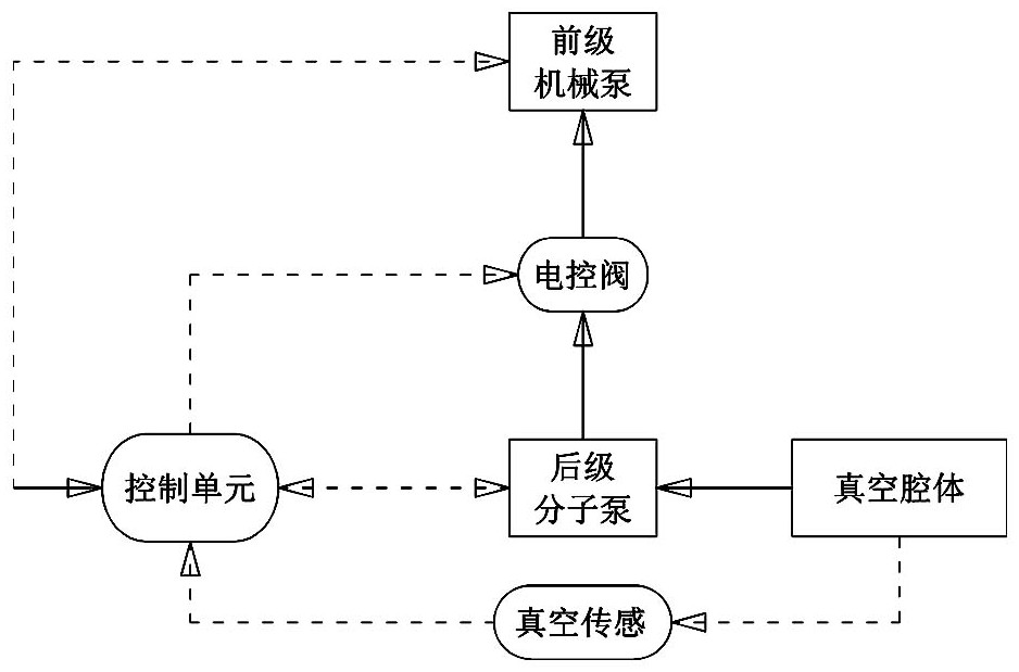
[0050] Such as figure 1 As shown, according to a specific embodiment of the present invention, a back-stage molecular pump control system for a vacuum system is provided, including a vacuum chamber, a back-stage molecular pump, a back-stage mechanical pump, an electric control valve, a vacuum sensor and a control system. unit.

[0051] The suction port of the rear-stage molecular pump is connected with the vacuum chamber, and the exhaust port of the rear-stage molecular pump is connected with the suction port of the front-stage mechanical pump through an electric control valve; the exhaust port of the front-stage mechanical pump is connected with the external atmospheric environment. The vacuum sensor is used to detect the vacuum degree in the vacuum chamber, and the vacuum sensor is arranged in the vacuum chamber or communicated with the vacuum chamber. The signal input interface of the control unit (such as a single-chip microcomputer controller) is respectively connected w...

Embodiment 2

[0067] Such as image 3 As shown, this embodiment provides another control method for the back-stage pump control system of the vacuum system described in Embodiment 1, including:

[0068] Step 1. The control unit judges whether the back-stage pump is turned on. Only after the front-stage pump is turned on, the control unit can control the opening of the electric control valve and the back-stage pump, so as to avoid damage to the back-stage pump when it is turned on alone;

[0069] Step 2, when the back-stage pump is turned on, the control unit reads the working temperature t, output power P and rotational speed n of the back-stage pump in real time through the built-in temperature sensor of the back-stage pump and the controller of the back-stage pump;

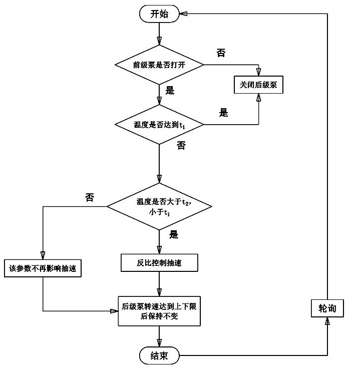
[0070] When the working temperature t of the back-stage pump is higher than or equal to the first preset temperature t 1 , it means that the working temperature of the back-stage pump is too high. Working in this state will ...

Embodiment 3

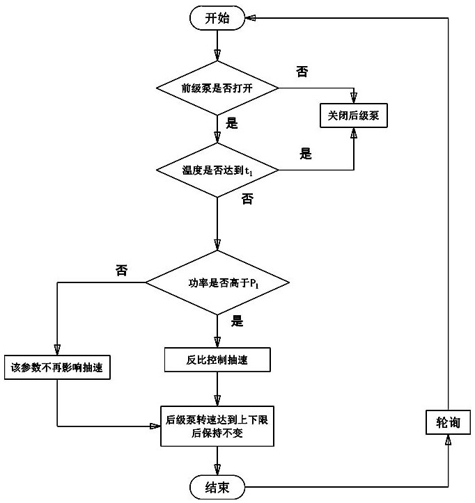
[0079] Such as Figure 4 As shown, this embodiment provides another control method for the back-stage pump control system of the vacuum system described in Embodiment 1, including:

[0080] Step 1. Determine whether the back-stage pump is turned on. Only after the front-stage pump is turned on, can the electric control valve and the back-stage pump be turned on;

[0081] Step 2, when the back-stage pump is turned on, the control unit reads the working temperature t of the back-stage pump and the vacuum degree in the vacuum chamber in real time through the temperature sensor arranged in the back-stage pump and the vacuum sensor of the back-stage pump;

[0082] When the working temperature t of the back-stage pump is higher than or equal to the first preset temperature t 1 , the control unit shuts down the back-stage pump through the controller of the back-stage pump;

[0083] When t 1 , indicating that the temperature of the back-stage pump is in the safe operating range. At ...


PUM


Abstract

The invention discloses a rear-stage pump control system and control method for a vacuum system. The rear-stage pump control system comprises a vacuum chamber, a rear-stage pump, a front-stage pump, an electric control valve, a vacuum sensor and a control unit, wherein a gas pumping port of the rear-stage pump communicates with the vacuum chamber, and a gas exhausting port of the rear-stage pump communicates with a gas pumping port of the front-stage pump through the electric control valve; and a signal input interface of the control unit is connected with the vacuum sensor and a built-in temperature sensor of the rear-stage pump, and a control output interface of the control unit is connected with a front-stage pump controller, a rear-stage pump controller and an input interface of an electric control valve controller. According to the rear-stage pump control system and control method for the vacuum system, by arranging the control unit, the front-stage pump and the rear-stage pump can be controlled to be started/stopped in real time conveniently, the rotating speed of the rear-stage pump can be adjusted conveniently, the vacuum degree of the vacuum chamber and the working temperature of the rear-stage pump are measured in time, the pumping speed of the rear-stage pump can be adjusted conveniently, the service life of the rear-stage pump is guaranteed, the working stability ofthe rear-stage pump is guaranteed, and power consumption is reduced; and the whole vacuum system has the advantages of being small in size and high in pumping speed, integration of the whole vacuum system is facilitated, and compared with a front-stage pump peripheral mode, the gas circuit structure is simplified.

Description

technical field [0001] The invention relates to a vacuum system, in particular to a back-stage pump control system and a control method for the vacuum system. Background technique [0002] In mass spectrometers, chromatographs and other instruments, the required high vacuum environment can reach the order of 10e-7mbar. In order to achieve the above vacuum degree, at present, the front-stage mechanical pump and the back-stage molecular pump are usually connected in series to achieve; that is, the front-stage mechanical pump Continuously work to extract the gas inside the vacuum chamber. When the vacuum degree in the vacuum chamber reaches a certain level, due to the limited pumping speed of the front-stage mechanical pump, the vacuum degree cannot continue to drop. At this time, restart the rear-stage molecular pump to extract the vacuum chamber The internal gas, because the pumping speed of the molecular pump of the latter stage is much higher than that of the mechanical pum...

Claims


Application Information

Patent Timeline
Patent Type & Authority Applications(China)
IPC IPC(8): F04B49/00F04B49/02F04B49/22F04B49/20F04B49/06
CPCF04B49/007F04B49/02F04B49/22F04B49/20F04B49/06
Inventor 尚元贺蔡克亚张子奇韩乐乐李向广
Owner AUTOBIO LABTEC INSTR CO LTD
Why Eureka
Try Eureka