Microstrip quasi-yagi antenna

A quasi-Yagi, microstrip line technology, applied in the field of antennas, can solve the problem of large antenna size

Pending Publication Date: 2020-10-02
HUNAN UNIV
View PDF0 Cites 0 Cited by
  • Summary
  • Abstract
  • Description
  • Claims
  • Application Information

AI Technical Summary

Problems solved by technology

[0004] Based on this, it is necessary to address the above technical problems and provide a microstrip quasi-Yagi antenna that can solve the problem of large antenna size caused by beam deflection.

Method used


Image

  • Microstrip quasi-yagi antenna
  • Microstrip quasi-yagi antenna
  • Microstrip quasi-yagi antenna

Examples


Embodiment Construction

[0027] In order to make the purpose, technical solution and advantages of the present application clearer, the present application will be further described in detail below in conjunction with the accompanying drawings and embodiments. It should be understood that the specific embodiments described here are only used to explain the present application, and are not intended to limit the present application.

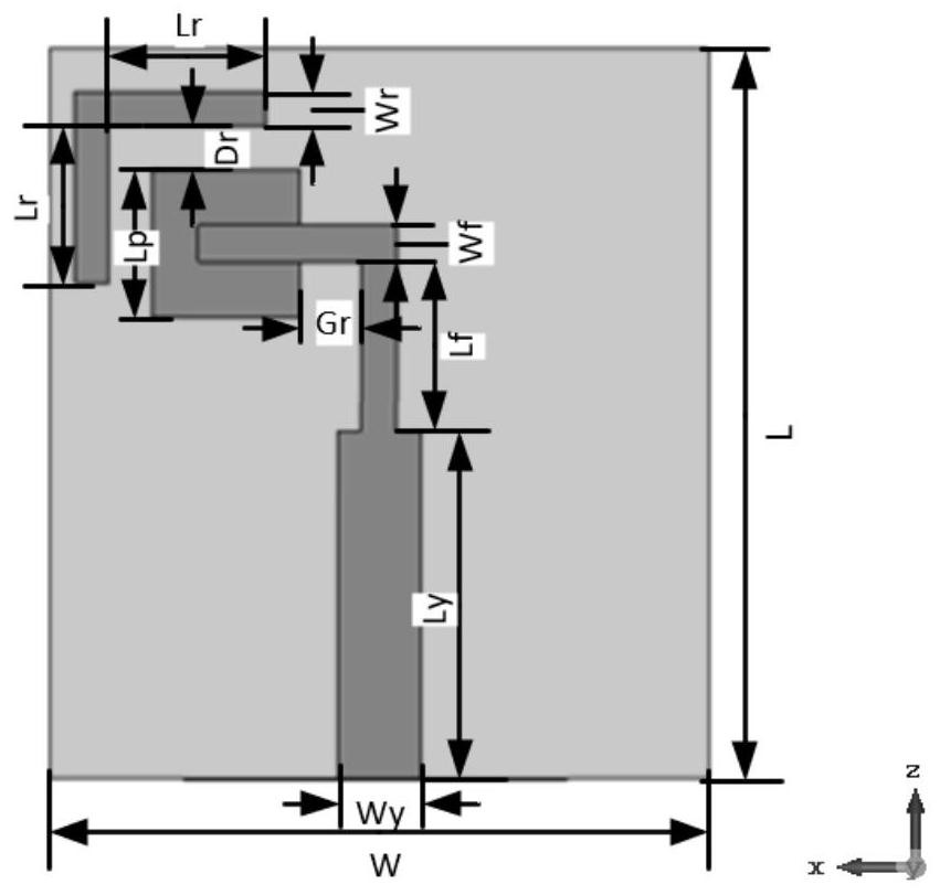
[0028] In one embodiment, such as figure 1 As shown, a microstrip quasi-Yagi antenna is provided, including:

[0029] Double-sided microstrip quasi-Yagi antenna and the director loaded on the double-sided microstrip quasi-Yagi antenna; the director includes: rectangular patch and right-angle microstrip line; the rectangular patch is loaded on the double-sided microstrip quasi-Yagi antenna The end of the excitation pole; the rectangular patch is used to expand the beam width and achieve beam deflection; the right-angle microstrip line is installed in a gap with the outer r...


PUM


Abstract

The invention relates to a microstrip quasi-yagi antenna, which comprises a double-sided microstrip quasi-yagi antenna and a director loaded on the double-sided microstrip quasi-yagi antenna, whereinthe director comprises a rectangular patch and a right-angle microstrip line, the rectangular patch is loaded at the tail end of the excitation pole of the double-sided microstrip quasi-yagi antenna,the rectangular patch is used for expanding the beam width and realizing beam deflection, the right-angle microstrip line and the outer right angle of the rectangular patch are mounted in a clearancefit manner, and the right-angle microstrip line is used for further expanding the beam width and improving the gain of the antenna. By adopting the method, the size of the microstrip quasi-yagi antenna can be greatly reduced under the condition of beam deflection guidance.

Description

technical field [0001] The present application relates to the technical field of antennas, in particular to a microstrip quasi-Yagi antenna. Background technique [0002] With the rapid development of wireless communication technology, as the most basic component - antenna, some special performances are constantly optimized and improved. For example, some highly directional local positioning systems (LPS), wireless sensor networks, and some scenarios in the fifth-generation mobile communication technology that are more and more widely used now require a highly directional and compact size or Small size antenna type. The microstrip quasi-Yagi antenna can meet such requirements. It is composed of a Yagi antenna with strong directivity and high gain but bulky and a low-profile, easy-to-process microstrip antenna. Combining the advantages of the two, it also has the characteristics of wider bandwidth and is more conducive to array formation, which greatly expands the applicati...

Claims


Application Information

Patent Timeline
IPC IPC(8): H01Q19/04H01Q19/30H01Q1/50H01Q5/50
CPCH01Q1/50H01Q19/04H01Q19/30H01Q5/50
Inventor 李高升申婉婷潘少鹏冯杨陈攀于杰贺佳港
Owner HUNAN UNIV
Why Eureka
Try Eureka