[0027] In order to make it easy to understand the technical means, creative features, goals and effects achieved by the present invention, the present invention will be further explained below in conjunction with specific embodiments.
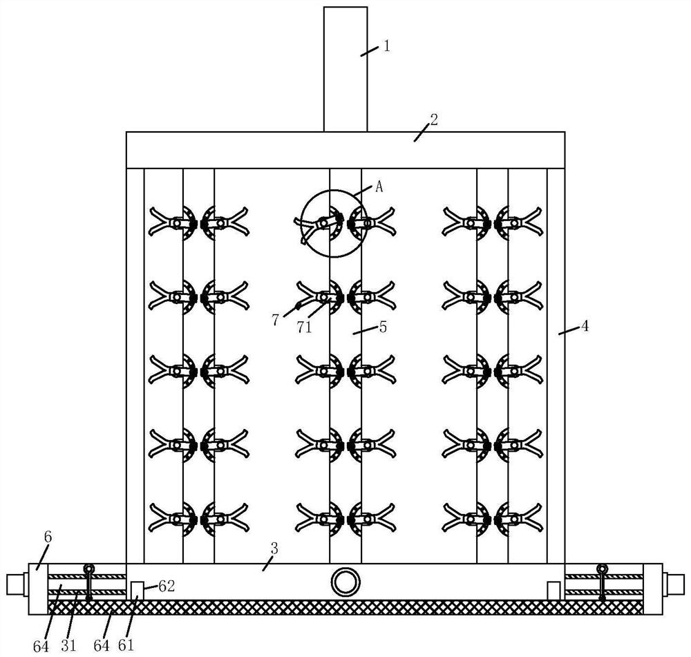
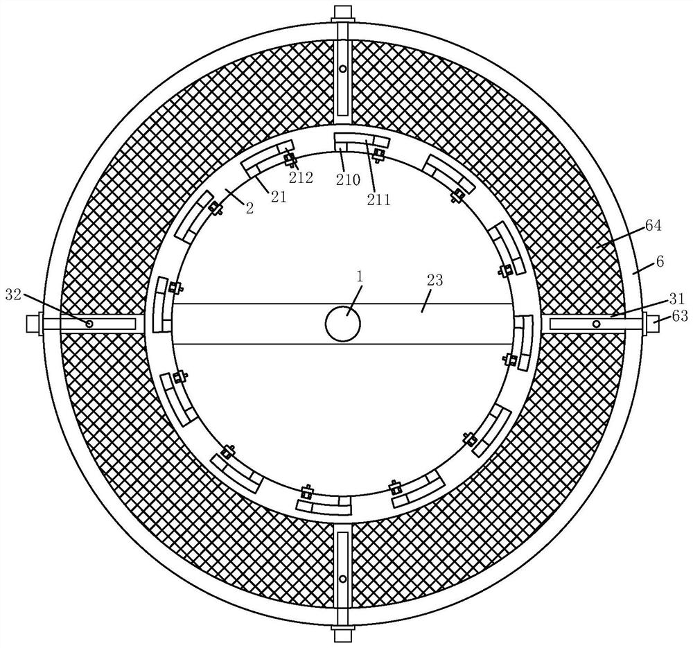
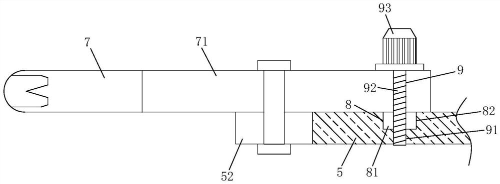
[0028] Such as Figure 1-Figure 7 As shown, the electroplating rack according to the present invention includes a hanging rod 1. The electroplating rack is placed in or taken out of the electroplating bath by pulling the hanging rod 1. The bottom end of the hanging rod 1 A connecting rod 23 is fixedly connected with the upper ring 2 at both ends of the connecting rod 23, the connecting rod 23 is used to fix and support the hanging rod 1, and the bottom of the upper ring 2 is fixedly connected with two connecting posts 4, The bottom ends of the two connecting columns 4 are fixedly connected with a lower ring 3, the upper ring 2 and the lower ring 3 are connected by the connecting column 4, a bottom ring 6 is provided under the lower ring 3, and the lower ring 3 Four evenly distributed sleeves 31 are arranged between the outer side wall and the bottom ring 6, and a plurality of evenly distributed mounting plates 5 are arranged between the upper ring 2 and the lower ring 3, and both sides of the mounting plate 5 are A plurality of evenly distributed fixing blocks 52 are fixedly connected, and a fixing plate 71 is hinged on the side of the fixing blocks 52 away from the hanging rod 1. When the angle of the clip 7 needs to be adjusted, the fixing plate 71 can be driven The clip 7 is rotated to adjust the angle of the clip 7, and the ends of the multiple fixing plates 71 away from the mounting plate 5 are fixedly connected with the clip 7, and the clip 7 is used to clamp the automobile parts that need to be electroplated. A second sliding structure 8 and a positioning structure 9 are provided between 71 and the mounting plate 5. The sides of the multiple mounting plates 5 close to the hanging rod 1 are all fixedly connected with L-shaped plates 51, and the multiple L-shaped plates 51 A hook 227 is provided on the upper side of the hook 227, and a telescopic rod 22 is fixedly connected to the top ends of the hooks 227, and a first sliding structure 21 is provided between the plurality of mounting plates 5 and the upper ring 2.
[0029] Specifically, the top ends of the plurality of telescopic rods 22 are fixedly connected with a connecting block 221, the top ends of the plurality of connecting blocks 221 are fixedly connected with a hinge block 220, and the inner side wall of the upper ring 2 is provided with a plurality of The hinge groove 24 is adapted to the hinge block 220. The hinge block 220 is hinged inside the hinge groove 24 so that the telescopic rod 22 can rotate on the upper ring 2 along the hinge groove 24 through the connecting block 221 and the hinge block 220.
[0030] Specifically, the telescopic rod 22 includes a sliding rod 222, a sliding cylinder 223, a sliding ring 225, a spring 224 and a limit ring 226, the sliding cylinder 223 is fixedly connected to the hook 227, and the sliding rod 222 is fixed to the hinge block 220 The bottom end of the sliding rod 222 is slidably connected to the inside of the sliding cylinder 223. The sliding rod 222 slides up and down inside the sliding cylinder 223 to increase or decrease the length of the telescopic rod 22. The sliding ring 225 is fixedly connected to the sliding cylinder 223. The bottom end of the rod 222, the sliding ring 225 is slidably connected to the inside of the sliding cylinder 223, the spring 224 is sleeved on the sliding rod 222 on the wall of the sliding cylinder 223, and the bottom end of the spring 224 is connected to the sliding ring 225 The limit ring 226 is slidably connected to the outer side wall of the sliding rod 222, and the outer side wall of the limit ring 226 is fixedly connected to the inner side wall of the sliding cylinder 223. The limit ring 226 can restrict the sliding ring 225 from sliding The sliding distance inside the cylinder 223 prevents the sliding rod 222 from slipping out of the sliding cylinder 223. The top end of the spring 224 is fixedly connected with the limiting ring 226. The outer side wall of the sliding cylinder 223 is fixedly connected with a handle 228, Pulling the handle 228 can drive the sliding cylinder 223 to slide on the outer side wall of the sliding rod 222, extending the length of the telescopic rod 22, so that the hook 227 can move up and down, and when the sliding cylinder 223 is pulled, the spring 224 will be forced on the limit ring 226 and the sliding ring 225 contract.
[0031] Specifically, the outer side walls of the plurality of L-shaped plates 51 are provided with a card hole 510 adapted to the hook 227, and the hook 227 penetrates the L-shaped plate 51 through the card hole 510, and the hook 227 and the card are provided The hole 510 can restrict the mounting plate 5 from sliding in the limiting groove 211. When the handle 228 is pulled to make the sliding cylinder 223 drive the hook 227 to move down inside the card hole 510, and then the handle 228 is pulled away from the card hole 510. Drive the hook 227 out of the card hole 510.
[0032] Specifically, the second sliding structure 8 includes a sliding block 81 and an arc-shaped sliding groove 82, the sliding block 81 is fixedly connected to the bottom end of the fixed plate 71, and the arc-shaped sliding groove 82 is opened on the mounting plate 5 away from the hanging On one side of the rod 1, the sliding block 81 is slidably connected to the inside of the arc-shaped sliding groove 82. When the fixed plate 71 rotates, the sliding block 81 is driven to slide in the arc-shaped sliding groove 82.
[0033] Specifically, the positioning structure 9 includes a positioning screw 92 and a positioning hole 91. The positioning hole 91 is provided with a plurality of positioning holes 91 evenly opened on the inner side wall of the arc-shaped sliding groove 82. The bottom end of the positioning screw 92 penetrates the fixing plate 71 and the sliding block 81, and the bottom end of the positioning screw 92 extends to the inside of the positioning hole 91, and the positioning screw 92 is threadedly connected to the fixing plate 71 and the sliding block 81. The positioning screw 92 is provided with a hand-tightening nut 93. By manually turning the hand-tightening nut 93, the positioning screw 92 can be manually rotated out of the positioning hole 91, so that the slider 81 can slide inside the arc-shaped chute 82, so that it can be moved The fixing block 52 enables the fixing block 52 to drive the clip 7 to rotate and adjust the angle of the clip 7. After the adjustment is completed, there is no need to use external tools to turn the thumb nut 93 by hand, and the thumb nut 93 to drive the positioning screw 92 is rotated, and the bottom end of the positioning screw 92 is screwed into the corresponding positioning hole 91, which can restrict the sliding of the slider 81 inside the arc-shaped chute 82 to prevent the fixed block 52 from moving, thereby making the fixed block 52 fixedly connected The clip 7 will not shake randomly, so that the clip 7 maintains an adjusted angle.
[0034] Specifically, the first sliding structure 21 includes a notch 210, a limiting block 212, and a limiting slot 211. There are two notches 210, a limiting block 212, and a limiting slot 211. The two notches 210 They are respectively opened on the inner side walls of the upper ring 2 and the lower ring 3, and the two limiting grooves 211 are respectively opened on the side of the upper ring 2 and the lower ring 3 close to each other, and are located at the same side of the upper ring 2 and the lower ring 3. The limiting groove 211 on the side communicates with the notch 210, the two limiting blocks 212 are fixedly connected to both ends of the mounting plate 5, and the two limiting blocks 212 are slidably connected to the two limiting slots 211. Inside, through the first sliding structure 21, the mounting plate 5 can be evenly arranged between the upper ring 2 and the lower ring 3.
[0035] Specifically, the bottom end of the inner side wall of the bottom ring 6 is fixedly connected with a protective net 64, the upper surface of the protective net 64 is fixedly connected with two symmetrically arranged positioning blocks 61, and the bottom of the lower ring 3 is provided with The two positioning blocks 61 are matched to the positioning groove 62, and the two positioning blocks 61 are both clamped in the inside of the positioning groove 62. When a part accidentally falls, the part will be blocked by the protective net 64, which can prevent Accidentally dropped parts enter the bottom of the electroplating bath.
[0036] Specifically, the side wall of the bottom ring 6 is slidably connected with four pin rods 63 that are adapted to the sleeve 31, and the four pin rods 63 pass through the bottom ring 6, and the four pin rods 63 The adjacent ends are inserted into the inside of the sleeve 31, the outer side wall of the sleeve 31 is provided with a pin hole 32, the pin rod 63 is provided with a plug pin, and the plug pin is clamped inside the pin hole 32, After the pin on the pin rod 63 is taken out of the pin hole 32, the pin rod 63 can be taken out of the sleeve 31, and the hanging rod 1 is lifted up to make the positioning block 61 on the protective net 64 escape the positioning groove 62. The bottom ring 6 and the protective net 64 are separated from the lower ring 3, and the operation of disassembling the bottom ring 6 is simple, which is convenient for subsequent cleaning of the electroplating hanger.
[0037] When in use, install the automobile parts that need to be electroplated in the clip 7, and perform the installation preparations before electroplating. In order to improve the plating effect of the parts, when the angle of the clip 7 needs to be adjusted, the screw cap 93 is screwed by hand Position the screw 92 to remove the positioning screw 92 from the original positioning hole 91, and then turn the fixing plate 71 to adjust the clip 7 to the required angle. The fixing plate 71 drives the slider 81 to slide along the arc-shaped chute 82. When the clip 7 reaches the preset angle When setting the angle, turn the thumb nut 93 by hand to drive the bottom end of the positioning screw 92 to rotate, so that the bottom end of the positioning screw 92 is screwed into the corresponding positioning hole 91, because the positioning screw 92 passes through the positioning hole 91 and the arc The bottom end of the sliding groove 82 is threadedly connected. The positioning structure 9 restricts the movement of the slider 81 and the fixed block 52, and restricts the fixed block 52 to drive the clip 7 to move, so that the clip 7 can maintain a preset angle, and the operation is simple. It is easy to use, and then by pulling the hanging rod 1, the hanging rod 1 drives the upper ring 2, the connecting column 4, and the lower ring 3 upward through the connecting rod 23, and the lower ring 3 drives the bottom ring 6 upward through the sleeve 31 and the protective net 64. Then place the electroplating hanger in the electroplating bath for electroplating. During this period, if parts accidentally fall, the parts will be blocked by the protective net 64, which can prevent accidentally dropped parts from entering the bottom of the electroplating bath. When the electroplating hanger is taken out, the parts are on the protective net 64. As the bottom ring 6 is taken out of the electroplating bath, it comes out. When the electroplating hanger needs to be cleaned after the electroplating, the mounting plate 5 can be removed from the upper ring 2. The sliding cylinder 223 slides on the outer side wall of the sliding rod 222 by pushing the handle 228 downwards. The spring 224 is forced to contract between the limit ring 226 and the sliding ring 225, and the hook 227 As the sliding cylinder 223 moves downwards in the card hole 510, pull the handle 228 away from the card hole 510. The handle 228 drives the hinge block 220 to rotate in the hinge groove 24 through the connecting block 221, so that the hook 227 rotates and Remove the card hole 510, and then push the mounting plate 5 so that the mounting plate 5 drives the limit blocks 212 at both ends to slide in the limit slot 211 until it slides to the gap 210, and the mounting plate 5 and the limit block 212 can be removed from the upper ring 2. It is simple and convenient to remove the mounting plate 5 from the lower ring 3. After removing the pin on the pin 63 from the pin hole 32, the pin 63 can be taken out of the sleeve 31, and the hanging rod can be lifted upward 1. The positioning block 61 on the protective net 64 can be separated from the positioning groove 62, and the bottom ring 6 and the protective net 64 are separated from the lower ring 3. The operation of disassembling the bottom ring 6 is simple, which is convenient for subsequent cleaning of the electroplating hanger and can improve The efficiency of cleaning plating racks.