[0035] The following describes the technical solutions in the embodiments of the present invention clearly and completely with reference to the accompanying drawings in the embodiments of the present invention; it is obvious that the described embodiments are only a part of the embodiments of the present invention; not all the embodiments. Based on the embodiments of the present invention; all other embodiments obtained by those of ordinary skill in the art without creative work; all belong to the protection scope of the present invention.
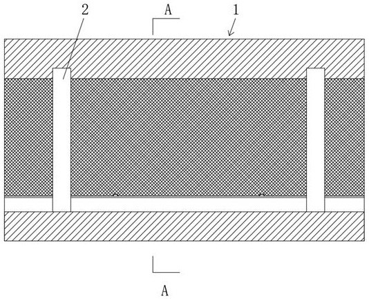
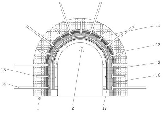
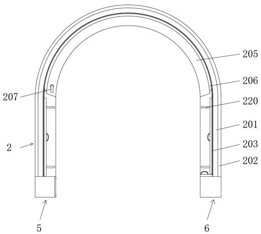
[0036] See Figure 1-13 , A smooth shotcrete supporting structure for a deep coal mine roadway, comprising a combined arch structure 1, on which a U-shaped arch 2 is provided.
[0037] The combined arch structure 1 includes a roadway rock layer 11, a concrete leveling layer 12 is provided on the inner wall of the roadway rock layer 11, a metal mesh 13 is provided on the inner wall of the concrete leveling layer 12, and metal bolts 14 and grouting are movably inserted on the metal mesh 13 The anchor rods 15, the metal anchor rods 14 and the grouting anchor rods 15 are alternately distributed. The metal anchor rods 14 and the grouting anchor rods 15 are fixedly inserted into the roadway rock layer 11 and the concrete leveling layer 12, and the inner wall of the metal mesh 13 is provided The concrete spraying layer 16 is provided with a covering layer 17 on the inner wall of the concrete spraying layer 16, and the parts where the winding device 5 and the fixing device 6 are in contact with the road surface can be opened with drains to discharge the leaking water and prevent the water from flowing to the center of the road.
[0038] The U-shaped arch 2 includes a U-shaped steel 201. The surface of the U-shaped steel 201 is fixedly connected to the inner wall of the concrete spraying layer 16. The U-shaped steel 201 is fixedly inserted into the cover layer 17, and the U-shaped steel 201 is provided with a warning device 3, U One end of the section steel 201 is provided with a winding device 5, and the other end of the U-shaped steel 201 is provided with a fixing device 6. U-shaped plates 202 are fixedly connected to the front and rear surfaces of the U-shaped steel 201. The U-shaped plates 202 and the inner wall of the concrete spray layer 16 Fixed connection, U-shaped plate 202 is fixed and embedded in the cover layer 17, U-shaped steel 201 is fixedly connected to the front and rear sides of U-shaped slide 203, the inner wall of U-shaped slide 203 is provided with track groove 204, U-shaped steel 201 The front and back of the accommodating box 205 are fixedly connected to the receiving box 205, the interior of the accommodating box 205 is movably embedded with an airbag 206, the airbag 206 is fixedly connected with an air nozzle 207, the other end of the air nozzle 207 extends to the outside of the receiving box 205, U-shaped steel A clamping cavity 208 is opened inside the clamping cavity 208, an edge holding device 4 is arranged inside the clamping cavity 208, a limit hole 209 fixedly connected with the clamping cavity 208 is opened on the inner wall of the U-shaped steel 201, and on the side of the U-shaped steel 201 A rectangular hole 220 fixedly communicated with the clamping cavity 208 is opened. The U-shaped steel 201 is provided with a cylindrical cavity 210 at one end thereof. The inner wall of the cylindrical cavity 210 is fixedly connected with a telescopic rod 211, and the outside of the telescopic rod 211 is movable A buffer spring 212 is sleeved, the left end of the telescopic rod 211 is fixedly connected with an arc-shaped inner tooth plate 213, one end of the buffer spring 212 is fixedly connected with the inner wall of the cylindrical cavity 210, and the other end of the buffer spring 212 is connected with the arc-shaped inner tooth plate 213 The screw 214 is fixedly connected to the right side of the arc-shaped inner toothed plate 213. The outer thread of the screw 214 is sleeved with an inner threaded sleeve 215, and the outer thread of the inner threaded sleeve 215 is fixedly sleeved with a limit ring 216, The position ring 216 is movably embedded in the inside of the U-shaped steel 201. The right end of the internally threaded sleeve 215 is fixedly connected with a rotating cap 217. The inner surface of the U-shaped steel 201 is provided with an adapting groove 218 that matches the rotating cap 217. The cap 217 is movably inserted into the fitting groove 218, and the rotating cap 217 is provided with a finger hole 219.
[0039] The warning device 3 includes an insulating cylinder 301, which is fixedly inserted on the inner surface of the U-shaped steel 201 and located in the middle. The bottom surface of the insulating cylinder 301 is fixedly connected with a warning light 302, and the bottom surface of the inner cavity of the insulating cylinder 301 is fixedly connected There is a conductive contact plate 303, a conductive spring 304 is fixedly connected to the left side of the inner cavity of the insulating cylinder 301, and the conductive spring 304 is matched with the conductive contact plate 303, and the top surface of the inner cavity of the insulating cylinder 301 is fixedly connected to a limit tube 305 And the bellows 306, the bellows 306 is movably inserted into the inside of the limit pipe 305, the top of the bellows 306 is fixedly connected with the top surface of the inner cavity of the insulating cylinder 301, and the bottom end of the bellows 306 is fixedly connected with an extension post 307, which extends The column 307 is movably inserted into the inside of the limit tube 305, the bottom end of the extension column 307 is fixedly connected with a piston plate 308, and the bottom surface of the piston plate 308 is fixedly connected with a mandrel 309, the mandrel 309 is matched with the conductive spring 304, the piston The top surface of the plate 308 is in contact with the bottom end of the limit tube 305, the piston plate 308 is slidingly connected to the inner wall of the insulating cylinder 301, and the piston plate 308 is fixedly connected to the top surface of the inner cavity of the insulating cylinder 301 with a telescopic piece 310 and a reset The spring 311 and the return spring 311 are movably sleeved on the outside of the telescopic member 310.
[0040] The crimping device 4 includes a guide rod 401, the end of the guide rod 401 is fixedly connected to the inner wall of the clamping cavity 208, and the outer movable sleeve of the guide rod 401 is sleeved with a crimping spring 402 and a crimping plate 403. One end is fixedly connected to the inner wall of the clamping cavity 208, the other end of the crimping spring 402 is fixedly connected to the crimping plate 403, the left side of the crimping plate 403 is fixedly connected with a clamping plate 404, and the other end of the clamping plate 404 It is movably plugged into the inside of the limiting hole 209. The clamping plate 404 is provided with a clamping cavity 405. The upper and lower surfaces of the clamping plate 404 are provided with rectangular perforations 406 fixedly connected to the clamping cavity 405. The inner wall of the clamping cavity 405 The positioning shaft 407 is movably connected to the positioning shaft 407, the torsion spring 408 is movably sleeved on the outside of the positioning shaft 407, the clamping triangle 409 is fixed to the outside of the positioning shaft 407, and the clamping triangle 409 is movably inserted into the rectangular perforation 406. One end of the spring 408 is fixedly connected to the inner wall of the clamping cavity 405, the other end of the torsion spring 408 is fixedly connected to the clamping triangle 409, the end of the clamping plate 403 is fixedly connected with a linkage bar 410, and the other end of the linkage bar 410 passes through the rectangle The hole 220 is fixedly connected with an edge holder 411, and the left side surface of the edge holder 411 is fixedly connected with a pulling handle 412.
[0041] The winding device 5 includes a winding box 501, the end surface of the winding box 501 is fixedly connected to the surface of the U-shaped steel 201, the left end of the winding box 501 is fixedly inserted into the inside of the covering layer 17, and the inside of the winding box 501 is fixedly connected with Guide wheel 502, a replacement port 503 is opened on the right side of the winding box 501, a sealing plate 504 is bolted on the right side of the winding box 501, a winding shaft 505 is movably sleeved on the inner wall of the winding box 501 , The other end of the winding shaft 505 extends to the inside of the cylindrical cavity 210 and is movably sleeved with its inner wall. The outside of the winding shaft 505 is fixedly sleeved with a fixed gear 506 and a torsion plate 507 located inside the cylindrical cavity 210. The fixed gear 506 is matched with the arc-shaped inner tooth plate 213. The external movable sleeve of the winding shaft 505 is sleeved with a spring 508 located inside the cylindrical cavity 210. One end of the spring 508 is fixedly connected with the surface of the winding shaft 505. The other end of 508 is fixedly connected to the inner wall of the cylindrical cavity 210, the outside of the winding shaft 505 is fixedly sleeved with a winding roller 509 located inside the winding box 501, and the outside of the winding roller 509 is wound with a strained cotton cloth 510. 510 is composed of water-changing cloth and plastic film. The water-changing cloth is directly in contact with the surface of the covering layer 17. The plastic film is fixedly adhered to the surface of the water-changing cloth and is in contact with the edge holder 411 and the airbag 206. The edge of the strained cotton cloth 510 is movably clamped inside the U-shaped slide rail 203, and the edge of the strained cotton cloth 510 is fixedly inserted with a clamping rod 511, and the end of the clamping rod 511 is slidingly inserted into the inside of the rail groove 204. The other end of the cotton cloth 510 extends to the outside of the winding box 501 and is slidably clamped between the crimping strip 411 and the covering layer 17, and between the airbag 206 and the covering layer 17, and is fixedly connected with a pressure plate 512. The top surface of the pressure plate 512 The lifting handle 513 is fixedly connected, the right end of the top surface of the pressure plate 512 is provided with a mounting groove 514, the inner bolt of the mounting groove 514 is fixed with a pressure piece 515, and the strain cotton cloth 510 is fixedly clamped between the pressure piece 515 and the inner wall of the installation groove 514 A plug rod 516 is fixedly connected to the bottom surface of the pressure plate 512, and a card joint 517 is fixedly connected to the bottom end of the plug rod 516.
[0042] The fixing device 6 includes a fixing box 61, the end surface of the fixing box 61 is fixedly connected with the surface of the U-shaped steel 201, the right end of the fixing box 61 is fixedly inserted into the cover layer 17, and a through hole 62 is opened on the left side of the fixing box 61 , The top surface of the fixed box 61 is provided with a control hole 63, the bottom surface of the pressing plate 512 is in contact with the top surface of the fixed box 61, the plug rod 516 is movably inserted into the control hole 63, and the card connector 517 is located in the fixed box 61 Inside, the control hole 63 is matched with the card connector 517, and the trigger device 7 and the force applying device 8 are arranged inside the fixing box 61.
[0043] The trigger device 7 includes an arc-shaped rod 701, the end of the arc-shaped rod 701 is fixedly connected with a fixing plate 702, and the fixing plate 702 is fixedly connected with the inner wall of the fixing box 61. The outer part of the arc-shaped rod 701 is fixedly sleeved with the limit ring 703. The outer movable sleeve of the shaped rod 701 is connected with a turning block 704 and a jacking spring 705. The top surface of the turning block 704 is in contact with the bottom surface of the limit ring 703. The bottom end of the jacking spring 705 is fixedly connected with a fixed plate 702. The other end of the lifting spring 705 is fixedly connected to the bottom surface of the turning block 704. The front and rear surfaces of the turning block 704 are fixedly connected with positioning rods 706. The other end of the positioning rod 706 is movably sleeved on the inner wall of the fixed box 61. The arc-shaped rod The center of the circle of 701 falls on the central axis of the positioning rod 706, and the inside of the turning block 704 is provided with a buffer cavity 707. The top surface of the inner cavity of the buffer cavity 707 is connected to the limiting piston 709 through a compression spring 708. The limiting piston 709 and the buffer cavity The inner wall of the 707 is slidably connected, and the other side of the limiting piston 709 is fixedly connected to the limiting chuck 710. The other end of the limiting chuck 710 extends to the outside of the turning block 704 and is movably clamped with the card joint 517. The left side of the turning block 704 A fixing hole 711 communicating with the buffer cavity 707 is opened on the side surface, and the fixing hole 711 is matched with the through hole 62.
[0044] The force applying device 8 includes a cylinder 81. The bottom surface of the cylinder 81 is fixedly connected with the bottom surface of the inner cavity of the fixed box 61. The bottom surface of the inner cavity of the cylinder 81 is connected with a piston disk 83 through a return spring 82. The piston disk 83 is slidingly connected with the inner wall of the cylinder 81 The top surface of the piston disk 83 is fixedly connected with a bearing rod 84. The top end of the bearing rod 84 extends to the outside of the cylinder 81 and is slidably connected to the bottom surface of the turning block 704. The back of the cylinder 81 is fixedly connected with an air pipe 85, The other end of the air pipe 85 extends to the inside of the limiting pipe 305 and is fixedly connected with the top end of the bellows 306.
[0045] working principle:
[0046] First, the combined arch structure 1 produces cracks under the action of in-situ stress, geological movement and other factors and causes the problem of water leakage. Then the leaked water is absorbed by the strained cotton cloth 510, and the leaked water spreads on the strained cotton cloth 510, and then the strained cotton cloth 510 discolors when exposed to water, used to remind the inspection miners, so that the miners can repair the corresponding parts in time, prevent the situation from further deterioration, the inspection process greatly reduces the observation requirements of the miners, saves time and effort, and responds The cotton cloth 510 guides the leaking water, so that the water flows along the surface of the covering layer 17, so as to prevent the water leaking from the top of the roadway from dripping directly on the center of the road surface, causing the problem of slippery in the center of the road surface, and helping to improve the working environment. Improve work safety. When cracks develop and cause the covering layer 17 to partially collapse and fall off, the fallen concrete blocks will inevitably apply tension to the strain cotton cloth 510 under the action of gravity, which prevents the covering layer 17 from locally disintegrating and falling off and hurting the miners. Problem, then the strain cotton 510 pulls the card connector 517 through the pressure piece 515, the mounting groove 514, the pressure plate 512, and the plug rod 516, and then the card connector 517 exerts a lifting force on the left end of the limit clamp 710, and then the limit clamp 710 The turning block 704 is turned clockwise with the positioning rod 706 as the central axis, and then the turning block 704 applies pressure to the bearing rod 84, and then the bearing rod 84 moves down with the piston disk 83, and then the gas pipe 85 and the bellows 306 The internal air pressure increases, and then the bellows 306 stretches and pushes the piston plate 308 to move downward, and then the piston plate 308 applies pressure to the conductive spring 304 through the ejector rod 309, then the conductive spring 304 is elastically bent and contacts the conductive contact plate 303, and then The power of the warning light 302 is turned on and emits a bright light to remind the inspection workers, so that the miners can repair the corresponding parts in time, prevent the situation from further deterioration, and the safety is high. Then the inspection workers see the strained cotton cloth 510 If the color changes or the warning light 302 lights up, then pull the pull handle 412. The pull handle 412 moves outwards with the clamping plate 404 through the crimping strip 411, the linkage strip 410, and the crimping plate 403, and then the limit hole 209 is paired The clamping triangle 409 applies pressure, the clamping triangle 409 flips and moves to the inside of the clamping cavity 405, then the clamping triangle 409 crosses the limit hole 209, and then the clamping triangle 409 is opened under the torsion force of the torsion spring 408, and then stops Pulling the pulling handle 412, the clamping triangle 409 is clamped on the inner surface of the U-shaped steel 201 under the elastic force of the clamping spring 402, thereby fixing the clamping strip 411, and separating the clamping strip 411 from the strained cotton cloth 510. Then the air inside the airbag 206 is released through the air nozzle 207 to separate the airbag 206 from the strained cotton cloth 510, and then the rotating cap 217 is rotated. The rotating cap 217 takes the female threaded sleeve 215 to rotate, and then the screw 214 is connected to the female threaded sleeve. 215 is pushed to the right under the action of the screw thread, and then the screw 214 moves to the right with the arc-shaped internal tooth plate 213 and moves with the fixed gear 50 6 is separated, the restriction on the winding shaft 505 is lifted, and then the pressure plate 512 is lifted by the lifting handle 513, and the pressure plate 512 is lifted by the plug rod 516 to the card connector 517, and the card connector 517 carries the turning block through the limit clip 710 704 is turned clockwise, and the turning block 704 moves down with the bearing rod 84 until the bearing rod 84 moves downward to the dead center position. At this time, the turning block 704 is in a horizontal state, the fixing hole 711 is aligned with the through hole 62, and then Use thin steel bars to insert through holes 62 and fixing holes 711 and apply thrust, then the thin steel bars directly apply thrust to the limiting piston 709, and then the limiting piston 709 with the limiting chuck 710 moves to the inside of the turning block 704, and then limiting The clamping head 710 is separated from the clamping joint 517, and then the clamping joint 517 is lifted out of the fixing box 61 by pulling the handle 513, the pressing plate 512, and the plug rod 516, and then the winding shaft 505 is brought under the torque of the mainspring 508 Rotate the winding roller 509 counterclockwise, and then the strained cotton cloth 510 is wound around the outside of the winding roller 509, and the strained cotton cloth 510 is retracted, and then the accident area is maintained and reinforced, and then the pressure piece 515 and the sealing plate 504 are removed with a wrench Then, pull out the strained cotton cloth 510 from the replacement port 503, and replace the strained cotton cloth 510.
[0047] The above; is only the preferred specific embodiments of the present invention; but the protection scope of the present invention is not limited to this; any person familiar with the technical field is within the technical scope disclosed by the present invention; according to the technical solution of the present invention The improvement concept and the equivalent replacement or change shall be included in the protection scope of the present invention.