Method for solving magnetic bias
A technology of biasing and blocking capacitors, applied in the field of biasing, can solve the hidden dangers of circuit safety, transformer saturation current, biasing and other problems, and achieve the effect of ensuring high-reliability operation, suppressing further deterioration, and improving reliability.
- Summary
- Abstract
- Description
- Claims
- Application Information
AI Technical Summary
Problems solved by technology
Method used
Image

Examples
Embodiment Construction
[0008] In order to realize the technical solution of the present invention and make it easier for more engineering and technical workers to understand and apply the present invention, how to solve the magnetic bias will be further described in conjunction with specific embodiments.
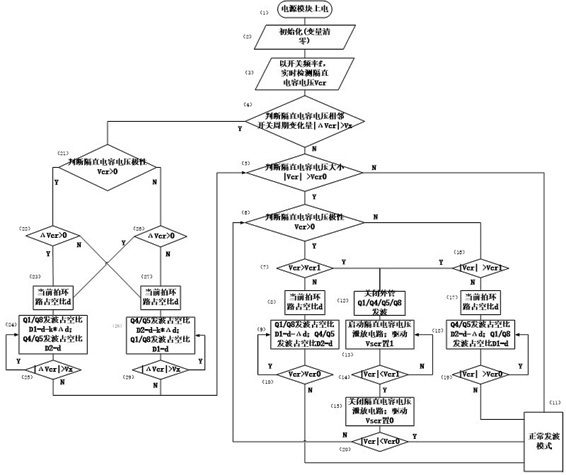
[0009] The concrete implementation strategy of the present invention is as follows:
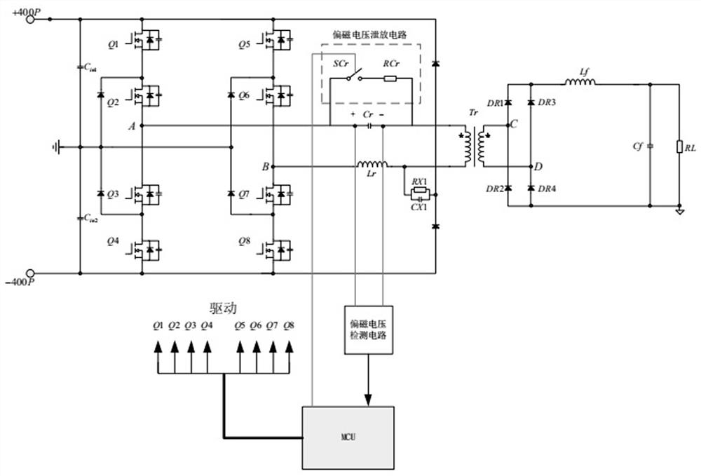
[0010] like figure 1 The three-level phase-shifted full-bridge topology is shown. Usually, in order to prevent magnetic bias, a DC blocking capacitor needs to be connected in series in the transformer excitation circuit. The fundamental purpose of the DC blocking capacitor is to solve the bias to a certain extent. The larger the value of the DC blocking capacitor , the stronger the ability to suppress the bias, but too large a DC blocking capacitor will increase the cost and volume, and in the case of output dynamic load, the duty cycle changes rapidly, and it is easier to generate bias, which leads to transforme...
PUM
 Abstract
Description
Claims
Application Information