Electric valve

A technology of electric valve and driving mechanism, which is applied in valve details, valve device, engine components, etc., can solve the problems of large volume of electric valve and large space occupied by fixed-axis gear set, and achieve the effect of small volume and compact structure.

Active Publication Date: 2020-10-09
HANGZHOU SANHUA RES INST CO LTD
View PDF7 Cites 3 Cited by
  • Summary
  • Abstract
  • Description
  • Claims
  • Application Information

AI Technical Summary

Problems solved by technology

However, the fixed shaft gear set takes up a lot of space, which makes the volume of the electric valve larger

Method used


Image

  • Electric valve
  • Electric valve
  • Electric valve

Examples


Embodiment Construction

[0026] Embodiments of the present invention will be described in detail below in conjunction with the accompanying drawings.

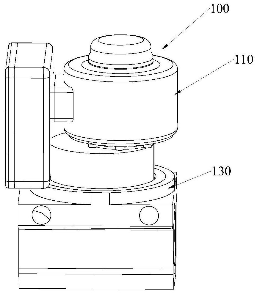
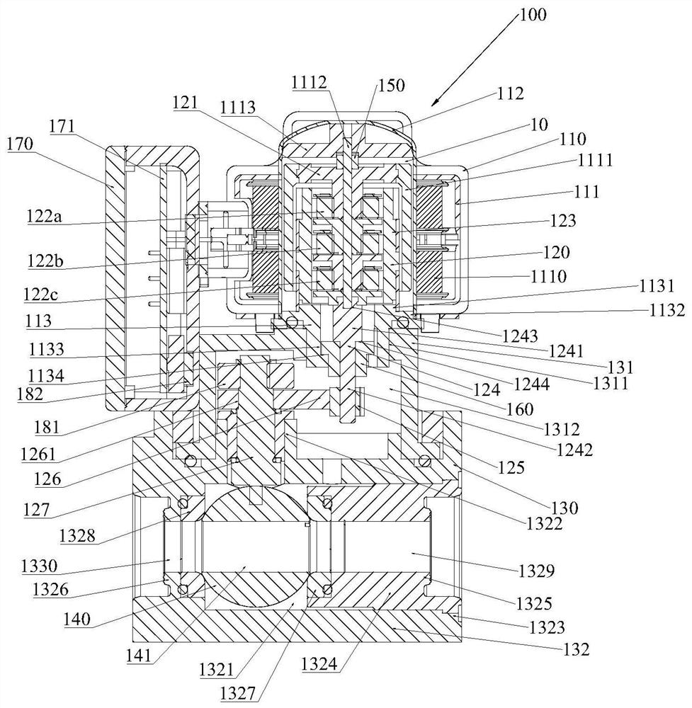
[0027] One embodiment of the present invention is as Figure 1 to Figure 8 shown. The electric valve 100 of this embodiment includes a driving mechanism 110 , a transmission assembly 120 , a valve body assembly 130 and a valve core 140 . Such as figure 2 As shown, the driving mechanism 110 includes a motor assembly 111, a sleeve 112 and a connecting seat 113. The motor assembly 111 includes a coil assembly 1110, a rotor assembly 1111 and a motor shaft 1112. The coil assembly 1110 is sleeved on the sleeve 112. The driving mechanism 110 also includes Positioning bracket 1113, positioning bracket 1113 includes a central hole, positioning bracket 1113 is located in the sleeve pipe 112 and fixed on the upper end of the sleeve pipe 112, the upper end of the motor shaft 1112 extends into the center hole of the positioning bracket 1113, the motor shaft 1112...


PUM


Abstract

The invention discloses an electric valve. The electric valve comprises a driving mechanism, a transmission assembly, a valve body assembly and a valve element, wherein the driving mechanism comprisesa rotor assembly, a sleeve and a connecting seat, the open end of the sleeve is fixedly connected with the connecting seat to form a sleeve cavity, the rotor assembly is contained in the sleeve cavity, the transmission assembly comprises a first transmission mechanism, the first transmission mechanism comprises a sun gear assembly, a fixed gear ring and at least one planet gear assembly, at leastone planet gear assembly comprises an output-stage planet gear assembly, the sun gear assembly is fixed to the rotor assembly, the fixed gear ring is fixed to the connecting seat, at least part of the fixed gear ring is located in the rotor assembly, the output-stage planet gear assembly comprises a planet gear, a first mounting plate and a second mounting plate, the planet gear is arranged between the first mounting plate and the second mounting plate, and the first mounting plate can directly or indirectly drive the valve element to act. According to the electric valve, the internal space of the rotor assembly is fully utilized, part of the structure of the transmission assembly can be relatively compact, and therefore the size of the electric valve is relatively small.

Description

【Technical field】 [0001] The invention relates to the technical field of fluid control, in particular to an electric valve. 【Background technique】 [0002] Electric valves are generally used for fluid switching or on-off. The current electric valves generally include a driving mechanism, a transmission assembly, and a valve body. The driving mechanism drives the valve core in the valve body to rotate through the transmission assembly to achieve fluid switching or on-off. . The transmission assembly is provided with a fixed shaft gear reduction mechanism, wherein the output torque of the motor is amplified by the fixed shaft gear set. However, the fixed shaft gear set takes up a lot of space, which makes the volume of the electric valve larger. 【Content of invention】 [0003] In order to solve the shortcomings of the above-mentioned electric valve, the present invention provides an electric valve, which includes a driving mechanism, a transmission assembly, a valve body a...

Claims


Application Information

Patent Timeline
Patent Type & Authority Applications(China)
IPC IPC(8): F16K5/06F16K31/53F16K37/00
CPCF16K5/06F16K5/0647F16K31/535F16K37/0041
Inventor 不公告发明人
Owner HANGZHOU SANHUA RES INST CO LTD
Why Eureka
Try Eureka