Heat exchange tube and air conditioner

A technology of heat exchange tubes and tube bodies, which is applied in the direction of heat sinks, tubular elements, heat exchange equipment, etc., and can solve the problems that heat exchange tubes cannot meet high-efficiency evaporation

Pending Publication Date: 2020-10-09
GREE ELECTRIC APPLIANCES INC
View PDF0 Cites 0 Cited by
  • Summary
  • Abstract
  • Description
  • Claims
  • Application Information

AI Technical Summary

Problems solved by technology

[0005] The embodiment of the present invention provides a heat exchange tube and an air conditioner to solve the technical problem that the heat exchange tube in the prior art cannot satisfy high-efficiency evaporation

Method used


Image

  • Heat exchange tube and air conditioner
  • Heat exchange tube and air conditioner
  • Heat exchange tube and air conditioner

Examples


Embodiment Construction

[0023] In order to make the objectives, technical solutions, and advantages of the present invention clearer, the present invention will be further described in detail below in conjunction with the embodiments and the drawings. Here, the exemplary embodiments of the present invention and the description thereof are used to explain the present invention, but not as a limitation to the present invention.

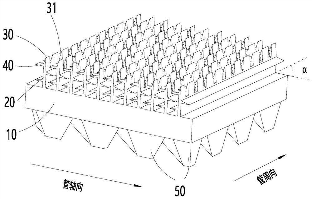
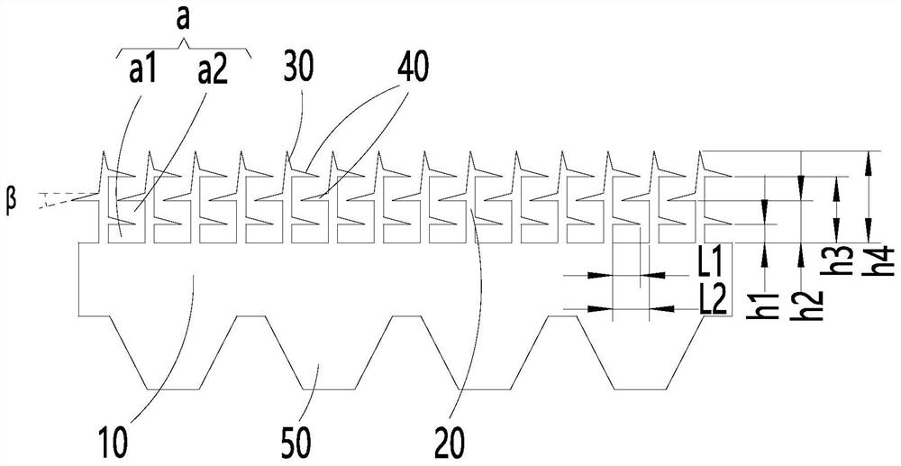
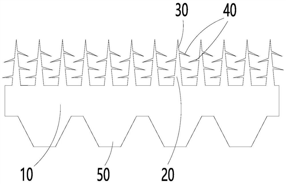
[0024] In order to solve the technical problem of the heat exchange tube in the prior art that cannot meet the high-efficiency evaporation and condensation, in the technical solution of the present invention, the fin 20 on the outer side of the tube body 10 is designed to improve the heat exchange tube. Thermal efficiency.

[0025] figure 1 with figure 2 The first embodiment of the heat exchange tube of the present invention is shown. The heat exchange tube includes a tube body 10 and a fin 20 arranged on the outer side of the tube body 10, and a lateral tooth structure 40 is form...


PUM


Abstract

The invention provides a heat exchange tube and an air conditioner. The heat exchange tube comprises a tube body and fins arranged on the outer side of the tube body, longitudinal tooth structures areformed on the tops of the fins, transverse tooth structures are formed on the side portions of the fins, between every two adjacent fins, and the transverse tooth structures on the two fins are arranged in a staggered mode in the vertical direction to form a zigzag evaporation cavity. Due to the fact that the heat exchange tube is provided with the zigzag evaporation cavity, compared with an existing heat exchange tube which can form a plurality of small evaporation cavities, more evaporation cores can be provided, more bubbles are generated, meanwhile, due to the semi-sealing performance ofthe zigzag evaporation cavity in the discharging process of the bubbles, and refrigerants in the cavities are subjected to the strong turbulent flow effect; and according to heat exchange tube, due tothe fact that the transverse tooth structures are arranged in the staggered mode, the paths of bubbles at the roots of the fins change continuously in the discharging process, the turbulent flow effect is further enhanced, and the evaporation efficiency is improved.

Description

Technical field [0001] The invention relates to the technical field of air conditioners, in particular to a heat exchange tube and an air conditioner. Background technique [0002] The heat pump unit has a more comfortable user experience due to both heating and cooling, and is gradually being promoted. Due to the special requirements of the heat exchange mode of the heat pump unit, the heat exchange tubes required by the unit must have the functions of evaporation and condensation. As for the existing heat exchange tubes, due to the different heat exchange principles of evaporation and condensation, the two tube structures are quite different. The evaporation tube follows the "nucleation theory" and tends to process various grooves or various micro-closed evaporation chambers; while the condenser tube is often based on the "Gregorig" effect and tends to process various sharp fins in order to reduce The thickness of the liquid film of the refrigerant fluid. [0003] At present, ...

Claims


Application Information

Patent Timeline
IPC IPC(8): F28F1/12F28F1/42F25B39/00
CPCF25B39/00F28F1/12F28F1/42F28F2215/10
Inventor 卓明胜胡东兵胡海利郑威
Owner GREE ELECTRIC APPLIANCES INC
Why Eureka
Try Eureka