Circuit board elastic sheet welding equipment

A technology for welding equipment and circuit boards, which is applied in the direction of assembling printed circuits with electrical components, and can solve the problems of low installation and welding efficiency of shrapnel, inaccurate welding accuracy, and low welding efficiency, and achieve good contact, firm installation, and increased installation speed Effect

Active Publication Date: 2021-01-01
重庆昕铭亚科技有限公司
View PDF13 Cites 0 Cited by
  • Summary
  • Abstract
  • Description
  • Claims
  • Application Information

AI Technical Summary

Problems solved by technology

[0006] Aiming at the problems in the prior art, the purpose of the present invention is to provide a circuit board shrapnel welding equipment to solve the existing problem that the shrapnel welding equipment can only install and weld one shrapnel at a time, so that the installation and welding efficiency of the shrapnel is low. , both the inner wall and the outer wall of the leg of the shrapnel need to be welded, while the existing one requires two processes. The second loading and unloading of the shrapnel makes the welding accuracy inaccurate, the welding efficiency is low, and the technical problem of slow production speed is caused.

Method used


Image

  • Circuit board elastic sheet welding equipment
  • Circuit board elastic sheet welding equipment
  • Circuit board elastic sheet welding equipment

Examples


Embodiment Construction

[0041] In order to make the technical means, creative features, goals and effects achieved by the present invention easy to understand, the present invention will be further elaborated below in conjunction with specific drawings. It should be noted that, in the case of no conflict, the embodiments and Features in the embodiments can be combined with each other.

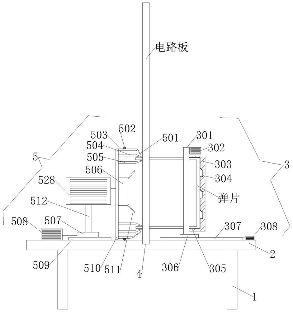
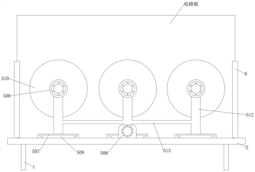
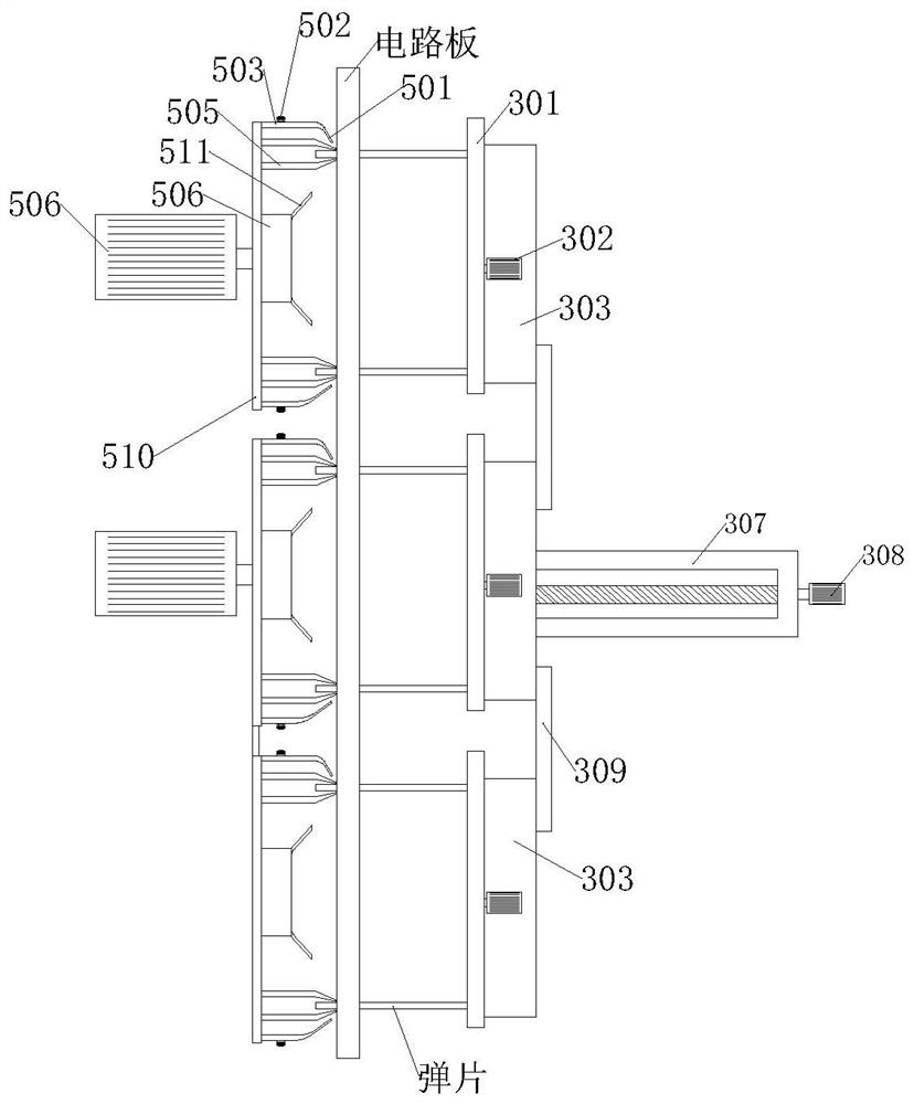
[0042] see Figure 1-11 , is a circuit board shrapnel welding equipment,

[0043] A circuit board shrapnel welding equipment, which is used in the production and assembly of circuit boards. It welds the shrapnel in the circuit board assembly process. The shrapnel is in the shape of a hollow cylinder in the middle. The workbench 2, the bottom of the workbench 2 is close to the four corners to be provided with support legs 1 standing upright on the bottom of the workbench 2, the middle part of the top of the workbench 2 is provided with a horizontal card slot 4, and the middle part of the top of the workbench 2 is loca...


PUM


Abstract

The invention provides circuit board elastic sheet welding equipment, which relates to the technical field of circuit board production and comprises a workbench with a horizontally placed workbench, atransverse clamping groove is formed in the middle of the top end of the workbench, and circuit board supporting clamping blocks erected at the top end of the workbench are symmetrically arranged inthe middle of the top end of the workbench and located at the two ends of the clamping groove. The circuit board is vertically installed at the top end of the workbench, the bottom end of the circuitboard is clamped in a clamping groove in the top end of the workbench, and the front side and the rear side of the circuit board are symmetrically clamped on circuit board supporting clamping blocks at the two ends of the clamping groove. According to the invention, the clamping plates are symmetrically pulled through the tension springs on the two sides, so that after the clamping plates are awayfrom the outer circle faces of the elastic pieces, the clamping plates are always balanced and centered at the top end of the second supporting rod, so that when the clamping plates clamp the elasticpieces next time, the attaching tightness of the clamping plates and the outer circle faces of the elastic pieces is improved, and the situation that the clamping plates swing disorderly, and consequently the clamping plates cannot be attached to the elastic pieces is avoided.

Description

technical field [0001] The invention relates to the technical field of circuit board production, in particular to a circuit board shrapnel welding equipment. Background technique [0002] The names of the circuit boards are: ceramic circuit board, alumina ceramic circuit board, aluminum nitride ceramic circuit board, circuit board, PCB board, aluminum substrate, high frequency board, thick copper board, impedance board, PCB, ultra-thin circuit board, ultra-thin Thin circuit boards, printed (copper etching technology) circuit boards, etc. The circuit board makes the circuit miniaturized and intuitive, and plays an important role in mass production of fixed circuits and optimizing the layout of electrical appliances. The circuit board can be called a printed circuit board or a printed circuit board. The characteristic of the shrapnel is that it is easy to bend in only one direction - the minimum stiffness plane, and has a large tensile stiffness and bending stiffness in the o...

Claims


Application Information

Patent Timeline
Patent Type & Authority Applications(China)
IPC IPC(8): H05K3/34
CPCH05K3/34
Inventor 梅皓琦
Owner 重庆昕铭亚科技有限公司
Why Eureka
Try Eureka