
A piston type constant temperature calorimeter

A technology of piston type and calorimeter, which is applied in the direction of material heat development, etc., can solve the problems of slow water inflow, probe pollution, etc., and achieve the effects of constant water volume, easy operation, and constant temperature of the working environment

Active Publication Date: 2017-06-23
XUZHOU TERRY INSTR & EQUIP CO LTD
View PDF5 Cites 0 Cited by
  • Summary
  • Abstract
  • Description
  • Claims
  • Application Information

AI Technical Summary

Problems solved by technology

The probe method is accurate in water quantification, and there is no influence of residual water after the inner cylinder is drained, but the water inlet speed of this method is relatively slow, and the probe is sometimes polluted

Method used


Image

  • A piston type constant temperature calorimeter
  • A piston type constant temperature calorimeter

Examples


Embodiment 1

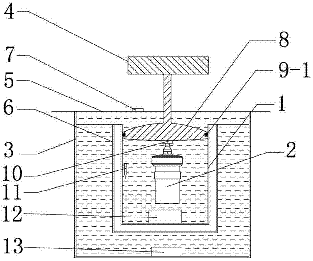
[0020] Such as figure 1 As shown, a piston-type constant temperature calorimeter includes an inner cylinder 1, an oxygen bomb 2, an outer cylinder 3, a machine cover 4 and a casing 5, the inner cylinder 1 is placed in the outer cylinder 3, and the inner cylinder 1 is placed in the outer cylinder 3. A middle cylinder 6 is provided between the cylinder 1 and the outer cylinder 3, the inner cylinder 1 and the middle cylinder 6 are sealed and hollowly connected as a whole, and the inner cylinder 1 and the middle cylinder 6 are completely submerged in the outer cylinder 3 in the water. Described machine cover 4 is installed on the casing 5 by hinge, is provided with piston 8 below machine cover 4, and the caliber of described piston 8 is slightly smaller than inner diameter of inner cylinder 1, and shape is consistent with inner cylinder 1 section shape, and the upper and lower surfaces of piston 8 Both are arc-shaped convex surfaces, which are convenient for the piston 8 to enter...

Embodiment 2

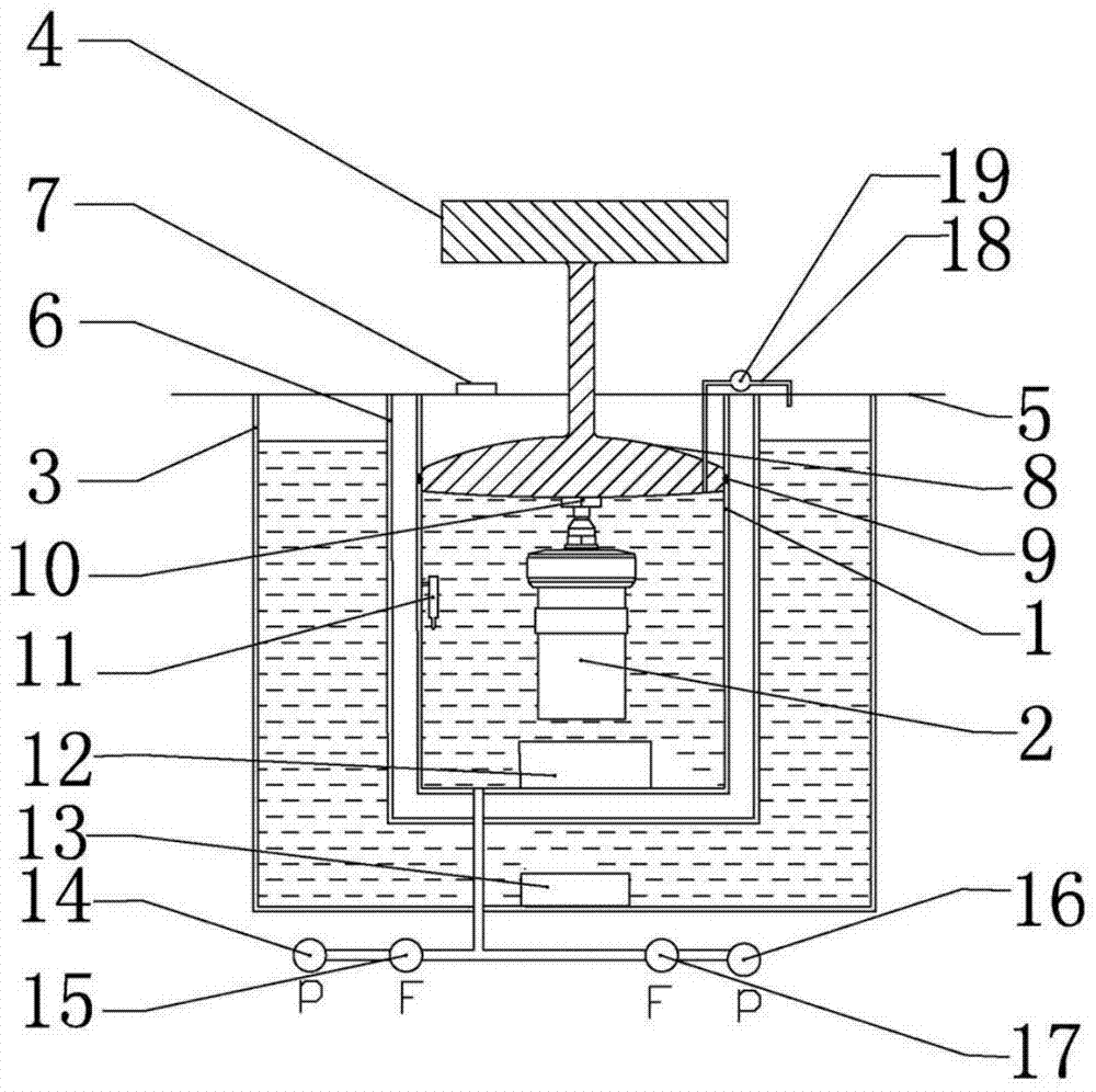
[0023] Such as figure 2 As shown, a piston-type constant temperature calorimeter includes an inner cylinder 1, an oxygen bomb 2, an outer cylinder 3, a machine cover 4 and a casing 5, the inner cylinder 1 is placed in the outer cylinder 3, and the inner cylinder 1 is placed in the outer cylinder 3. A middle cylinder 6 is provided between the cylinder 1 and the outer cylinder 3, and the space between the inner cylinder 1 and the middle cylinder 6 is hollow. The machine cover 4 is installed on the casing 5 through a lifting mechanism, and the bottom of the machine cover 4 A piston 8 is provided, and the diameter of the piston 8 is slightly smaller than the inner diameter of the inner cylinder 1, and its shape is consistent with the section shape of the inner cylinder 1. 8. The sticky water on the upper and lower surfaces of the inner cylinder 1 can be quickly dripped clean. The bottom of the piston 8 is provided with an ignition electrode 10 through which the sample in the oxy...


PUM


Abstract

The invention discloses a piston-type constant temperature calorimeter, which relates to the field of analytical instruments for the calorific value of combustible substances, and comprises an inner cylinder (1), an oxygen bomb (2), an outer cylinder (3), a machine cover (4) and a machine The shell (5), the middle cylinder (6) is arranged between the inner cylinder (1) and the outer cylinder (3), the space between the inner cylinder (1) and the middle cylinder (6) is hollow, and the casing (5) is provided with a positioning device (7), a piston (8) is arranged under the machine cover (4), the upper and lower surfaces of the piston (8) are arc-shaped convex surfaces, and the position where the piston (8) contacts the inner cylinder (1) is provided with a sealing ring (9) , the bottom of the piston (8) is provided with an ignition electrode (10), the inner cylinder (1) is provided with a temperature measuring probe (11) and an inner cylinder stirring mechanism (12), and the outer cylinder (3) is provided with an outer cylinder stirring mechanism ( 13). The piston-type constant-temperature calorimeter of the invention can perform accurate and fast water quantification during measurement, and improves the measuring accuracy and measuring efficiency of the calorimeter.

Description

technical field [0001] The invention relates to the field of analytical instruments for the calorific value of combustible substances, in particular to a piston-type constant temperature calorimeter. Background technique [0002] The calorific value of combustion is one of the most important indicators to evaluate the quality of coal, which is directly related to the price of coal transactions. The instrument used to measure the calorific value of coal is a calorimeter, also known as a calorimeter, calorimeter or oxygen bomb. Calorimeters can be divided into constant temperature type, adiabatic type and double dry type according to the principle. Among them, the constant temperature type has a simple structure and is easy to maintain, and is currently the most widely used. The constant temperature calorimeter is generally composed of an outer cylinder, an inner cylinder, an oxygen bomb, a machine cover, a casing, a stirring system, an ignition device, a control system, etc...

Claims


Application Information

Patent Timeline
Patent Type & Authority Patents(China)
IPC IPC(8): G01N25/22
Inventor 张洪张徐州陈猛裴君伟张锋
Owner XUZHOU TERRY INSTR & EQUIP CO LTD
Learn More