Method and device for measuring channel flow coefficient of pressurized cabin of passenger aircraft

A channel flow and flow measurement technology, which is applied in the direction of measuring devices, detecting fluid flow by measuring differential pressure, volume/mass flow generated by mechanical effects, etc., can solve structural and interior design weight redundancy waste, influence verification, structure and interior strength assessment can not meet the requirements, etc., to improve the forward design ability, avoid redundant waste, and improve the effect of iterative input ability

Active Publication Date: 2021-11-02
XI AN JIAOTONG UNIV
View PDF6 Cites 0 Cited by
  • Summary
  • Abstract
  • Description
  • Claims
  • Application Information

AI Technical Summary

Problems solved by technology

If the selection of the flow coefficient is smaller than the actual value, the weight of the structure and interior design will have a high redundant waste; if the selection of the flow coefficient is larger than the actual value, the strength assessment of the structure and interior may be Unable to meet the requirements, need to be reinforced, or even redesigned
Studies have shown that inaccurate selection of flow coefficient may increase the pressure relief load to 400%, leading to major safety hazards during flight and affecting the verification of airworthiness provisions of various airworthiness authorities, thus restricting domestic large aircraft from going abroad

Method used


Image

  • Method and device for measuring channel flow coefficient of pressurized cabin of passenger aircraft
  • Method and device for measuring channel flow coefficient of pressurized cabin of passenger aircraft
  • Method and device for measuring channel flow coefficient of pressurized cabin of passenger aircraft

Examples


Embodiment 1

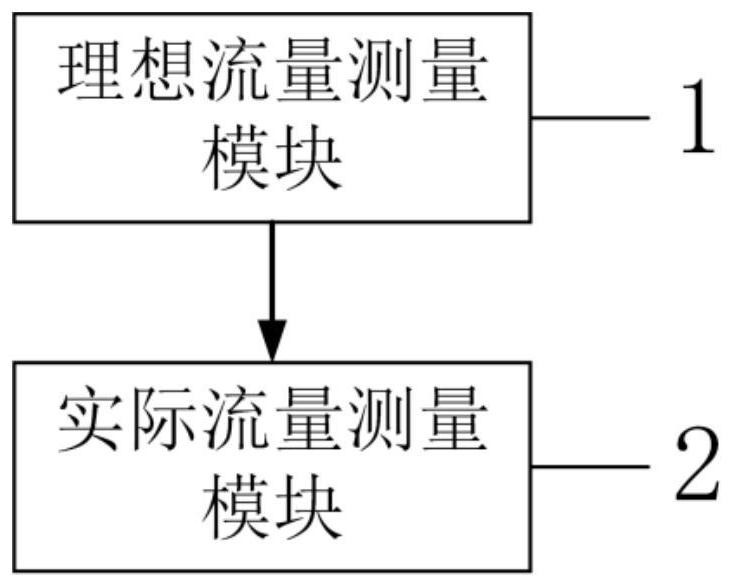
[0039] See figure 1 , figure 1 It is a schematic diagram of a device module for measuring the channel flow coefficient of a pressurized cabin of an airliner provided by an embodiment of the present invention. An embodiment of the present invention provides a device for measuring the flow coefficient of the pressurized cabin channel of a passenger aircraft, including an ideal flow measurement module 1 and an actual flow measurement module 2, wherein,

[0040] The ideal flow measurement module 1, the ideal flow measurement module 1 includes a test chamber, which is used to adjust the inlet pressure and outlet pressure of the test chamber. When the inlet pressure of the test chamber reaches the inlet target pressure value and the outlet pressure reaches the outlet target pressure value, respectively measure The inlet pressure and outlet pressure of the test chamber, and the measurement of the gas temperature in the test chamber to obtain the ideal flow m according to the inlet p...

Embodiment 2

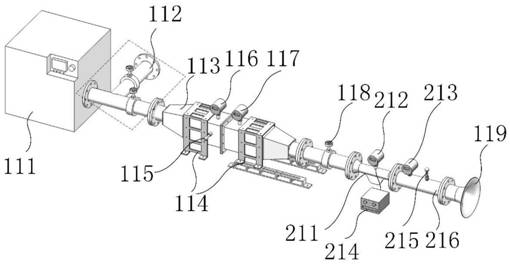
[0051] See figure 2 , figure 2 It is a structural schematic diagram of a negative pressure device for measuring the channel flow coefficient of a pressurized cabin of an airliner provided by an embodiment of the present invention. When the test chamber is the first test chamber 113, the ideal flow measurement module 1 includes a screw pump 111, a first valve group 112, a first fixture 114, a first temperature sensor 115, a first outlet pressure sensor 116, a first inlet pressure Sensor 117, second valve group 118 and first bell mouth 119, wherein,

[0052] The screw pump 111 is connected to the first end of the first valve group 112, the first end of the first test chamber 113 is connected to the second end of the first valve group 112, and the second end of the first test chamber 113 is connected to the second end of the second valve group 118. First end, the first fixing device 114 is installed on the outer wall of the first test chamber 113, and the first temperature se...

Embodiment 3

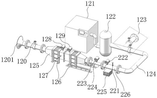
[0067] See Figure 5 , Figure 5 It is a structural schematic diagram of a positive pressure device for measuring the channel flow coefficient of a pressurized cabin of an airliner provided by an embodiment of the present invention. The test chamber is the second test chamber 125, and the corresponding ideal flow measurement module 1 includes a screw compressor 121, an air storage tank 122, a third valve group 123, an outlet pipeline 124, a second fixing device 126, a third temperature sensor 127, a second Three inlet pressure sensors 128, a third outlet pressure sensor 129, a fourth valve group 120 and a second bell mouth 1201, wherein,

[0068] The screw compressor 121 is connected to the first end of the air storage tank 122, the second end of the air storage tank 122 is connected to the first end of the third valve group 123, and the second end of the third valve group 123 is connected to the first end of the outlet pipeline 124 , the second end of the outlet pipe 124 is...


PUM


Abstract

The invention discloses a method and device for measuring the channel flow coefficient of a pressurized cabin of an airliner, which includes an ideal flow measurement module and an actual flow measurement module, wherein the ideal flow measurement module is used to adjust the inlet pressure and outlet pressure of the test cabin. When the inlet pressure and outlet pressure of the chamber reach the target pressure value, measure the inlet pressure and outlet pressure of the test chamber respectively, and measure the gas temperature in the test chamber, and obtain the ideal flow m according to the inlet pressure, outlet pressure and gas temperature 2 The actual flow measurement module is connected to the first end or the second end of the test chamber, and is used to measure the actual flow m flowing through the actual flow measurement module when the inlet pressure and outlet pressure of the test chamber reach the target pressure value 1 . The invention can accurately obtain the flow coefficients of various typical circulation passages by performing the flow coefficient measurement test on various typical measuring devices of the pressurized cabin of the large passenger aircraft.

Description

technical field [0001] The invention belongs to the field of flow coefficient measurement, and in particular relates to a method and a device for measuring the flow coefficient of a pressurized cabin channel of an airliner. Background technique [0002] The pressurized cabin is one of the important devices to improve the flight performance and safety performance of modern long-distance passenger aircraft. It can effectively avoid the adverse effects of high-speed airflow, low temperature and other factors on the personnel on the aircraft, and provide a comfortable cabin environment to meet the physiological needs of the personnel on the aircraft. . The pressurization process is to deliver the pressurized air to the cockpit (including the passenger cabin and cockpit, etc.) under normal or emergency conditions, and then discharge it out of the machine through the exhaust valve. During the flight, the air conditioning component provides regulated air into the cockpit, and the ...

Claims


Application Information

Patent Timeline
Patent Type & Authority Patents(China)
IPC IPC(8): G01M9/06G01F1/34G01F1/36G01F1/44B64F5/60
CPCB64F5/60G01F1/34G01F1/36G01F1/44G01M9/06
Inventor 雷蒋杨玺徐进鲁瑞山张科
Owner XI AN JIAOTONG UNIV
Why Eureka
Try Eureka