Supercharge Your Innovation With Domain-Expert AI Agents!

Fault detection circuit and method for vehicle-mounted indicator lamp

A fault detection circuit and indicator light technology, applied in the field of automotive technology, can solve problems such as inability to meet customer requirements, increase use costs, and inability to provide users with prompts, achieving low cost, high commercial value, and simple methods.

Pending Publication Date: 2020-10-09
M2MOTIVE TECH INC
View PDF0 Cites 1 Cited by
  • Summary
  • Abstract
  • Description
  • Claims
  • Application Information

AI Technical Summary

Problems solved by technology

[0004] In existing technical solutions, it is common to diagnose short-circuit to ground and short-circuit to voltage without providing on-position detection. In such a technical solution, only short-circuit to ground and short-circuit to voltage can be realized. In the case of damage or failure to install, it is impossible to provide prompts to the user, and it is also unable to meet customer requirements; and even if there is a technical solution for on-site detection, it is necessary to add a current detection device, and the current sensor is used to realize the on-site detection of the indicator light. If the indicator light is damaged or not installed, the current sensor can quickly detect that the circuit has no current and alarm, and provide prompt information to the user. Although this meets the customer's requirements, it undoubtedly increases the cost of use.
[0005] At present, there is no technical solution that can solve the above-mentioned technical problems, specifically, there is no fault detection circuit and method for vehicle-mounted indicator lights.

Method used


Image

  • Fault detection circuit and method for vehicle-mounted indicator lamp
  • Fault detection circuit and method for vehicle-mounted indicator lamp
  • Fault detection circuit and method for vehicle-mounted indicator lamp

Examples


Embodiment Construction

[0032] In order to better clearly express the technical solution of the present invention, the present invention will be further described below in conjunction with the accompanying drawings.

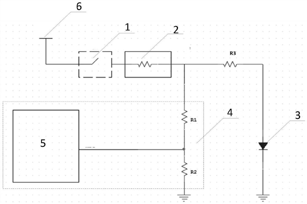
[0033] figure 1 It shows a specific embodiment of the present invention, a schematic diagram of the circuit structure of a fault detection circuit of a vehicle-mounted indicator light. Those skilled in the art understand that the present invention can not only be applied to the technical field of fault detection of a vehicle-mounted indicator light, but also can be used for For fault detection of other electronic equipment, on-board indicator lights are of great significance to driving safety, and users and manufacturers need to be reminded when a fault occurs. Therefore, manufacturers put forward relatively high requirements for on-board indicator light fault diagnosis, which requires component manufacturers A reliable and convenient diagnostic method is provided. The fault detection c...


PUM


Abstract

The invention discloses a fault detection circuit for a vehicle-mounted indicator lamp. Whether the vehicle-mounted indicator lamp breaks down or not is judged according to circuit voltage values of acontrol switch in a closed state and an open state, and the method comprises the steps that a series circuit composed of the control switch (1) and a resistance current sensor (2) is connected with aparallel circuit composed of the vehicle-mounted indicator lamp (3) and a detection resistor (4); one end of the vehicle-mounted indicator lamp (3) is connected with the series circuit, and the otherend of the vehicle-mounted indicator lamp (3) is grounded; the detection resistor (4) comprises a first resistor R1 and a second resistor R2 which are connected in series, the first resistor R1 is connected with the series circuit, and the second resistor R2 is grounded; and one end of the series circuit is connected with a power supply (6). The method is simple, convenient to use, low in cost and accurate in detection, and has extremely high commercial value.

Description

technical field [0001] The invention belongs to the application field of automobile technology, and in particular relates to a fault detection circuit and method of a vehicle indicator light. Background technique [0002] The car dashboard is a device that reflects the working conditions of the various systems of the vehicle. The common ones are fuel indicator light, washer fluid indicator light, electronic throttle indicator light, front and rear fog light indicator lights and warning lights, and the on-board indicator light is the indicator light in the car dashboard, and its function is to diagnose vehicle The major systems on the car and the real-time feedback of the working status of each system of the car are displayed to the driver through various indicator lights. [0003] The on-board indicator light is of great significance to driving safety. It is necessary to remind the user and the manufacturer when a fault occurs. Therefore, the manufacturer puts forward relat...

Claims


Application Information

Patent Timeline
IPC IPC(8): G01R31/44
CPCG01R31/44
Inventor 雷强瞿三朗
Owner M2MOTIVE TECH INC
Features
  • R&D
  • Intellectual Property
  • Life Sciences
  • Materials
  • Tech Scout
  • Unparalleled Data Quality
  • Higher Quality Content
  • 60% Fewer Hallucinations
Learn More