
FPGA-based video interface diagnosis method and system

A technology of video interface and diagnosis method, applied in the parts of TV system, TV, color TV, etc., can solve problems that cannot be determined at a deeper level, lack of investigation/diagnosis problems, no way to start, etc., to meet the needs of diagnosis. Effect

Active Publication Date: 2020-10-09
CHENGDU FOURIER ELECTRONICS TECH +1
View PDF12 Cites 2 Cited by
  • Summary
  • Abstract
  • Description
  • Claims
  • Application Information

AI Technical Summary

Problems solved by technology

[0003] Due to the wide variety of interfaces, users can only judge the presence or absence of signals by observing the images on the display device. When encountering video interface problems, they often have no way to start, and cannot determine the specific location of the problem at a deeper level. At this time, there is a need for A guide for troubleshooting problems, but currently, there is a lack of effective guidance for troubleshooting / diagnosing problems

Method used


Image

  • FPGA-based video interface diagnosis method and system
  • FPGA-based video interface diagnosis method and system
  • FPGA-based video interface diagnosis method and system

Examples


Embodiment

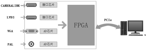
[0079] Such as image 3 Shown is the structure diagram of the FPGA-based video interface diagnosis system provided for this example.

[0080] Design VGA, PAL, CAMERALINK and LVDS video input interfaces on the board, and reserve multiple FPGA IO interfaces at the same time, which can easily support the expansion of other types of video interfaces, meet more video interface diagnostic needs, and adapt to different Application occasions.

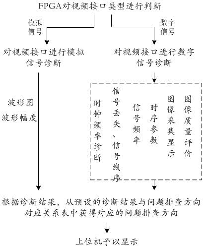
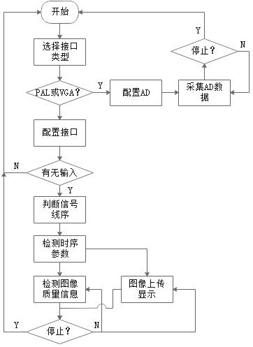
[0081] Among them, CAMERALINK and LVDS are digital video signals. For digital signals, it can diagnose video interface signal loss, interface line sequence errors, image timing parameters, image quality evaluation and other items. PAL and VGA are analog signals, which are converted by AD. FPGA collects the converted digital signals and transmits them to the upper computer. The upper computer draws the waveform diagram according to the received data, and at the same time marks the waveform amplitude and other information It is convenient for users ...


PUM


Abstract

The invention relates to an FPGA-based video interface diagnosis system and method. The FPGA-based video interface diagnosis system is established through using an onboard FPGA. The method comprises the steps that: the FPGA judges a video interface type, namely, performs analog signal diagnosis when the video interface type is an analog signal interface, and performs digital signal diagnosis whenthe video interface type is a digital signal interface; acquiring a corresponding problem troubleshooting direction from a preset corresponding relation table of diagnosis results and problem troubleshooting directions according to the diagnosis result. Analog signal diagnosis is implemented by the steps that the FPGA collects data obtained after AD conversion and sends the data to an upper computer through using a PCIe interface in a DMA transmission mode, and the upper computer carries out oscillogram description on the received data and marks waveform amplitude. The digital signal diagnosisis implemented by the steps that signals collected by an interface chip are sequentially subjected to video interface signal clock frequency diagnosis, video interface signal loss and signal line sequence diagnosis, video interface signal frequency diagnosis, image time sequence parameter measurement, image collection and display and image quality evaluation by means of the FPGA. According to theFPGA-based video interface diagnosis system and the method, the diagnosis result is used for guiding the user to troubleshoot the problem.

Description

Technical field [0001] The invention relates to video image interface diagnosis, in particular to a method and system for video interface diagnosis based on FPGA. Background technique [0002] Video images have developed faster and faster in recent years, and video image interface standards have become more and more abundant, from analog PAL, VGA, YPbPr to digital DVI, HDMI, SDI, DP and other interfaces. [0003] Due to the wide variety of interfaces, users can only use the display device to observe the image to determine whether the signal is present. When encountering a video interface problem, it is often impossible to start, and cannot determine the specific problem in a deeper level. A guide for troubleshooting, but currently, there is no effective guide for troubleshooting / diagnosing problems. Summary of the invention [0004] In view of the above-mentioned shortcomings and deficiencies of the related prior art, the present invention provides an FPGA-based video interface dia...

Claims


Application Information

Patent Timeline
Patent Type & Authority Applications(China)
IPC IPC(8): H04N5/268H04N5/765H04N17/00G06F13/32G06T1/20G06T7/00
CPCH04N5/268H04N5/765H04N17/00G06T7/0002G06F13/32G06T1/20G06T2207/10016G06T2207/30168Y02D10/00
Inventor 孙风雷谢洪波
Owner CHENGDU FOURIER ELECTRONICS TECH
Learn More