
Double swirl type air purifier

An air purifier, eddy current technology, applied in the direction of air quality improvement, air conditioning system, air flow control components, etc., can solve the problems of multiple humidity and hygiene, small contact area, dehumidification problems, etc., to achieve easy maintenance and management, high capture efficiency , Easy to lightweight effect

Active Publication Date: 2020-10-09
共功有限公司
View PDF6 Cites 1 Cited by
  • Summary
  • Abstract
  • Description
  • Claims
  • Application Information

AI Technical Summary

Problems solved by technology

It’s just that in the above-mentioned prior art, when the above-mentioned forced suction force combines water and air to form a vortex, when passing through the guide portion and the first and second fins for forming a vortex, the time for the air to contact with the water It is very short, therefore, the harmful components in the air will not come into contact with the water phase at the moment when the vortex is generated, but will be discharged as it is, and there is a problem that the air purification level cannot meet the expectation, and the noise generated during the high-speed and high-pressure air suction is large. , there is a problem that it is not suitable for home use
[0010] In addition, the higher humidity of the outlet air will cause dehumidification problems, and the re-scattering of multiple humid pollutants will cause hygiene and sterilization problems
Existing disc-type technology also absorbs water droplets on the disc, thereby enlarging the surface area, therefore, in the case of rotating the disc at high speed, water splashes will be generated, and similar to the water jet type, it will cause multiple problems of humidity and sanitation , in the case of rotating at low speed, the contact area per unit time is small and the efficiency is low

Method used


Image

  • Double swirl type air purifier
  • Double swirl type air purifier
  • Double swirl type air purifier

Examples


Embodiment Construction

[0041] Hereinafter, a detailed description will be given with reference to a preferred embodiment of the present invention.

[0042] For reference, the structures of the present invention described below that are the same as those of the prior art can refer to the above-mentioned prior art, and separate detailed descriptions are omitted.

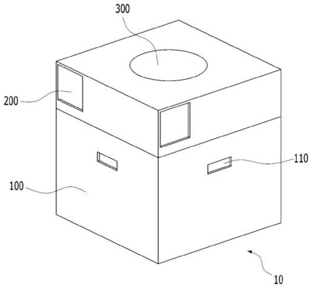
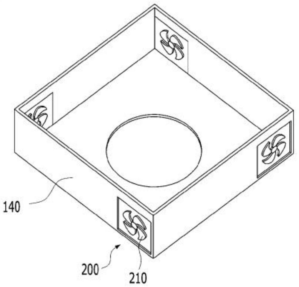
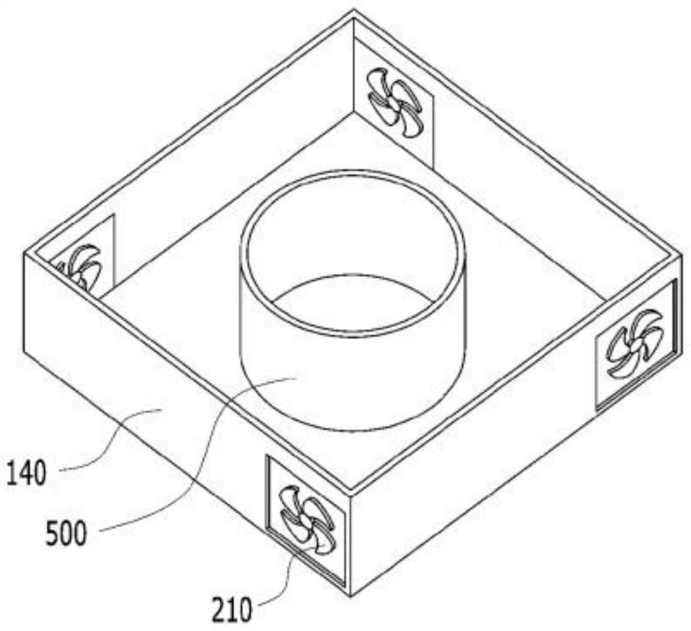
[0043] FIG. 1 is a perspective view of a double vortex air cleaner according to an embodiment of the present invention, and FIGS. 2a and 2b are exploded views of a cover of the double vortex air cleaner according to an embodiment of the present invention.

[0044] As shown in FIG. 1 , FIG. 2 a , and FIG. 2 b , the double vortex air cleaner 10 of the present invention includes a main body 100 , a suction part 200 , a discharge part 300 and a rotating part 400 disposed on one side of the main body.

[0045] The main body part 100 is used as a storage part containing a liquid, and the liquid is used to purify the air introduced inside the doubl...


PUM


Abstract

The present invention relates to a double swirl type air purifier and, more specifically, to a double swirl type air purifier comprising: a main body unit which accommodates a fluid for purifying inflow air therein; a suction unit located at one side of the main body unit, the suction unit sucking the inflow air; and a discharge unit located at a set position in the main body, the discharge unit discharging outflow air introduced from the main body unit, wherein the main body unit comprises a rotation unit located at a part of the lower side of the main body unit, the rotation unit rotating the liquid. Thus, the air purifying efficiency can be increased by increasing the contact area between the fluid swirled by the rotation unit and the inflow air swirled by the inflow pressure of the suction unit.

Description

technical field [0001] The present invention relates to a double vortex type air cleaner, and in more detail, relates to a method for supplying air with a certain pressure from the air inflow inlet side of the air cleaner and a suction force for forcibly sucking in the air inside the air cleaner so that the air The vortex generated by combining with water is divided into 1st and 2nd, thereby expanding the contact area between water and air, improving the capture of harmful components and air purification capabilities, and increasing the efficiency of the air purifier. Double vortex air purifier. Background technique [0002] The present invention relates to a dual vortex type air cleaner, and more particularly, to a dual vortex type air cleaner which is improved to operate more efficiently and economically by reducing maintenance costs and enhancing performance. [0003] With the stepping into the modern society, due to various complex problems of air pollution such as indus...

Claims


Application Information

Patent Timeline
IPC IPC(8): F24F3/16F24F13/08
CPCF24F8/133Y02A50/20F24F8/192A61L2209/22A61L9/122A61L2209/134F24F13/10F24F13/28
Inventor 李宣彦
Owner 共功有限公司
Learn More