Tube punching die with improved structure

A technology of structural improvement and punching die, applied in the direction of perforation tools, metal processing equipment, manufacturing tools, etc., can solve the problems of easily stuck in vertical holes, deformation of mandrels, difficult to fall out, etc. The effect of cracking, improving strength and prolonging service life

Pending Publication Date: 2020-10-13
JIANGSU BOJUN IND TECH
View PDF0 Cites 0 Cited by
  • Summary
  • Abstract
  • Description
  • Claims
  • Application Information

AI Technical Summary

Problems solved by technology

[0002] At present, the hole position processing of the side wall of the pipe parts is carried out. One is to position the pipe and then use the drilling method to process the hole position; Fix the mandrel on the lower die, set a vertical hole through the mandrel from top to bottom, punch the pipe with the punch on the upper die, and the waste material will fall out from the vertical hole of the mandrel. Large size punching, the vertical hole size C on the mandrel is very large, the mandrel is very thin at the side wall of the vertical hole, punching for a long time, it is easy to cause the mandrel to deform, crack or even break, and the waste is easy to jam In the vertical hole, it is difficult to fall out, causing a lot of trouble for pipe punching

Method used


Image

  • Tube punching die with improved structure
  • Tube punching die with improved structure
  • Tube punching die with improved structure

Examples


Embodiment

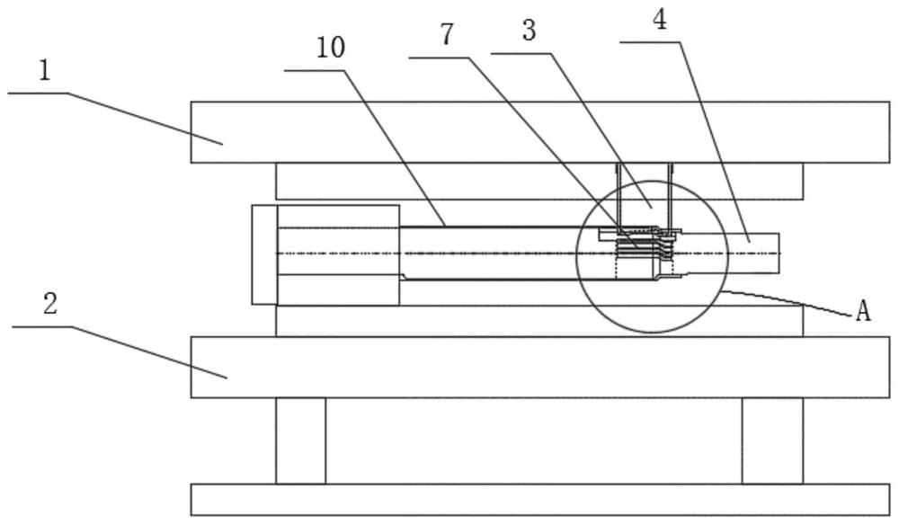
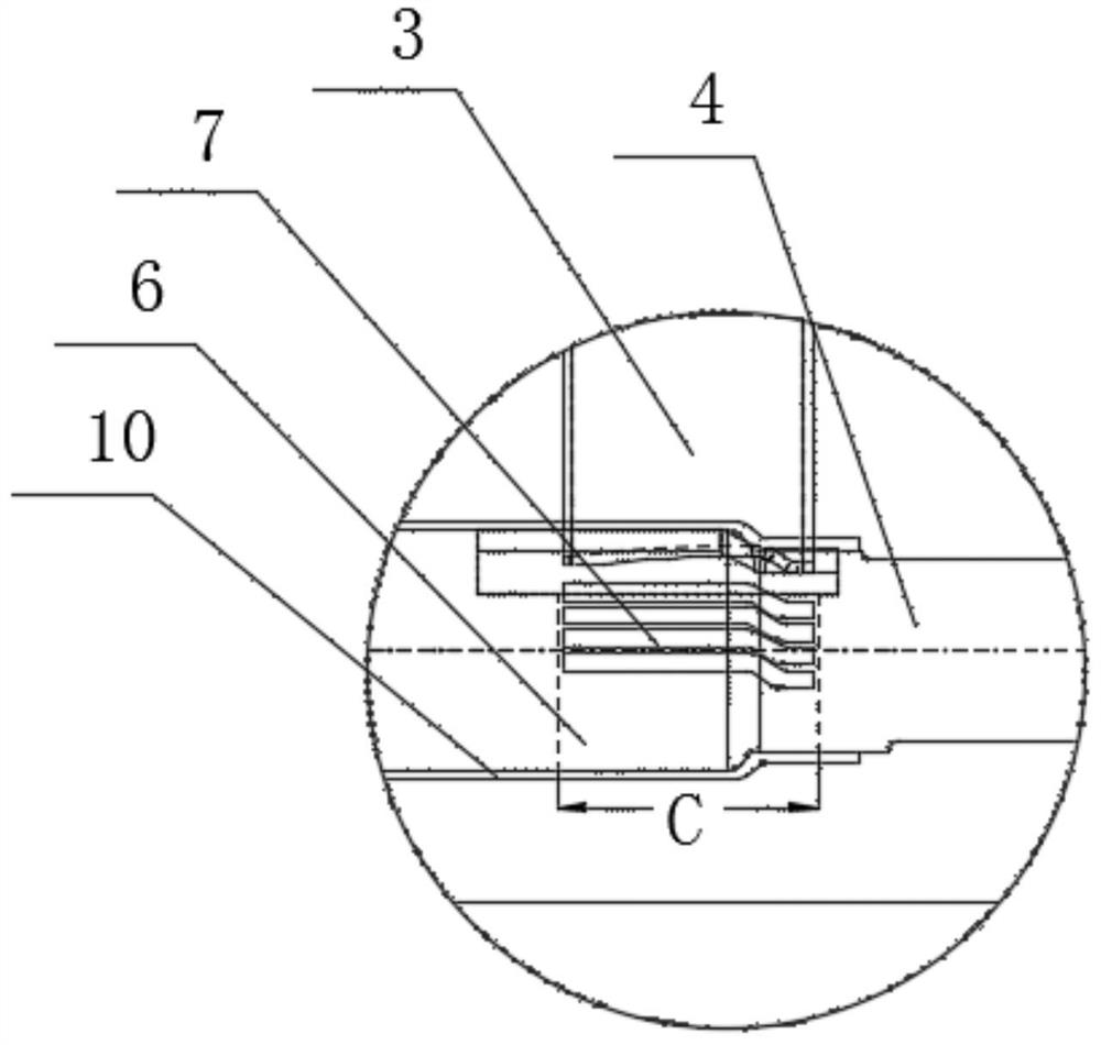
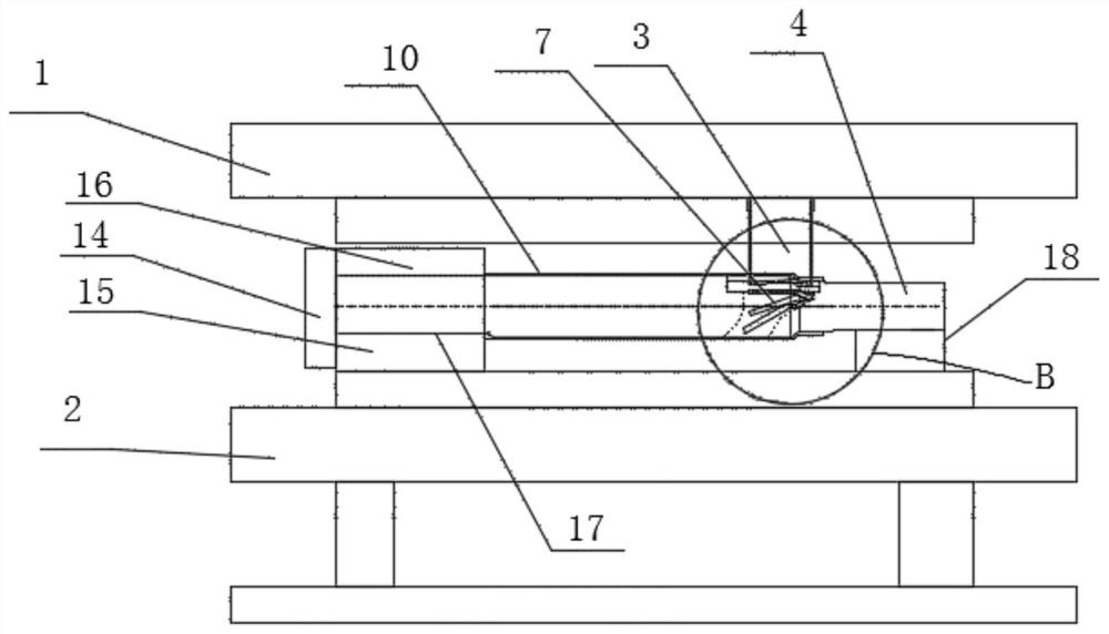
[0023] Example: A pipe punching die with an improved structure, comprising an upper die 1, a lower die 2, a punch 3, a core rod 4, and a core rod positioning device. The upper die 1 can move up and down and is located directly above the lower die 2. , The punch 3 is fixedly installed on the upper mold 1, the core rod positioning device is installed on the lower mold 2, the core rod positioning device can fix the core rod 4 on the lower mold 2, and the pipe to be punched can just be sleeved on On the outer circumference of the core rod 4, the core rod 4 is provided with a die hole 5 and a blanking hole 6. The punch 3 can be inserted into the die hole 5 of the core rod 4. The side wall of the punch 3 and the core rod 4 The side wall of the die hole 5 is formed with a cutting edge, the upper end of the blanking hole 6 and the lower end of the die hole 5 are directly connected to form a radial hollow structure penetrating the core rod 4, and a side wall of the blanking hole 6 is for...


PUM


Abstract

The invention discloses a tube punching die with an improved structure. The tube punching die comprises an upper mould, a lower mould, a punch, a mandrel and a mandrel positioning device, wherein theupper mould can be positioned above the upper mould in a lifting motion mode; the punch is fixedly mounted on the upper mould; the mandrel positioning device is mounted on the lower mould; the mandrelpositioning device can fix and position a mandrel onto the lower mould; a tube to be punched just can sleeve the outer side of the periphery of the mandrel; a concave mould hole and an unloading holeare formed in the mandrel; the punch can be inserted into the concave mould hole of the mandrel; the side wall of the punch and the side wall of the concave mould hole of the mandrel define an oppositely-split cutting edge; the upper end of the unloading hole and the lower end of the concave mould hole are oppositely jointed to form a radial hollow-out structure which penetrates through the mandrel; and a guide inclined surface which tilts towards the other side wall of the unloading hole is formed on the side wall of the unloading hole. The tube punching die improves discharge smoothness, increases the thickness of the side wall of an unloading hole part of the mandrel, improves strength of the mandrel; and the mandrel is not liable to deform and crack after long-time use, so that the service life of the mandrel is prolonged.

Description

Technical field [0001] The invention relates to a hardware mold, in particular to a pipe punching mold with an improved structure. Background technique [0002] At present, the sidewall hole position processing for pipe parts is to process the hole position by drilling after the pipe is positioned; the other is to use a punching die for processing, and the pipe is placed on the mandrel. Fix the mandrel on the lower mold. The mandrel is provided with a vertical hole penetrating from top to bottom. The pipe is punched by the punch on the upper mold, and the waste material falls flat from the vertical hole of the mandrel. Large-size punching, the vertical hole size C on the mandrel is very large, the mandrel is located at the side wall of the vertical hole is very thin, long-term punching, it is easy to cause the mandrel to deform, crack or even break, and the waste is easy to jam In the vertical hole, it is difficult to fall out, causing a lot of trouble for the pipe punching. Su...

Claims


Application Information

Patent Timeline
Patent Type & Authority Applications(China)
IPC IPC(8): B21D28/34B21D28/28
CPCB21D28/28B21D28/34
Inventor 齐美文
Owner JIANGSU BOJUN IND TECH
Why Eureka
Try Eureka