Laser life test fixing clamp

A fixed fixture and life test technology, applied in the field of lasers, can solve the problems of inconvenient installation and disassembly, easily damaged instruments, simple structure, etc., and achieve the effect of preventing left and right movement

Active Publication Date: 2020-10-13
苏州鼎智瑞光智能科技有限公司
View PDF6 Cites 0 Cited by
  • Summary
  • Abstract
  • Description
  • Claims
  • Application Information

AI Technical Summary

Problems solved by technology

[0004] The purpose of the present invention is to provide a laser life test fixture, to solve the problems in the above-mentioned background technology that it is inconvenient to install and disassemble, simple in structure and easy to damage the instrument

Method used


Image

  • Laser life test fixing clamp
  • Laser life test fixing clamp
  • Laser life test fixing clamp

Examples


Embodiment Construction

[0022] The following will clearly and completely describe the technical solutions in the embodiments of the present invention with reference to the accompanying drawings in the embodiments of the present invention. Obviously, the described embodiments are only some, not all, embodiments of the present invention. Based on the embodiments of the present invention, all other embodiments obtained by persons of ordinary skill in the art without making creative efforts belong to the protection scope of the present invention.

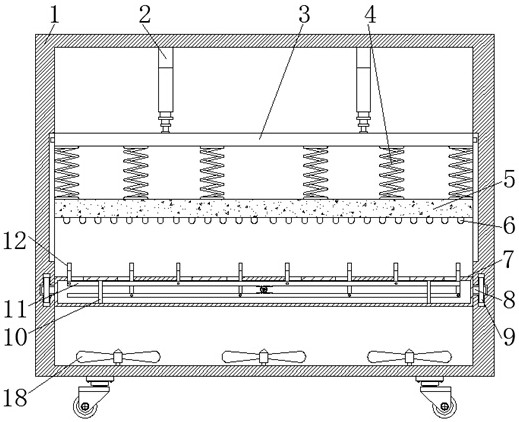
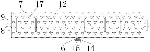
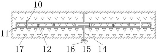
[0023] see Figure 1-7 , the present invention provides a technical solution: a laser life test fixture, including a main box 1, an electric telescopic rod 2, a fixed plate 3, a spring 4, a soft rubber plate 5, a soft rubber pad 6, an inner box 7, Rotating shaft 8, roller 9, support rod 10, movable rod 11, limit plate 12, gear 13, rotating rod 14, handwheel 15, bolt 16, through hole 17 and cooling fan 18, main box body 1 top is fixed with The electric telesco...


PUM


Abstract

The invention discloses a laser life test fixing clamp comprising a main box body, an inner box body, a supporting rod and a through hole. An electric telescopic rod is fixed at the top end of the main box body; the lower end of the electric telescopic rod is fixed to a fixing plate, a spring is fixed to the lower end of the fixing plate, a movable rod is connected with a gear, the gear is fixed to a rotating rod, a hand-cranking wheel is fixed to the tail end of the rotating rod and connected with a bolt, the through hole is formed in the inner box body, and a cooling fan is fixed to the bottom end of the main box body. According to the laser life test fixing clamp, the limiting plates are matched in pairs to fix the laser; the laser is prevented from moving left and right; movement of the limiting plates is controlled through the movable rod to fix the laser; compared with bolt fixing, the laser is more convenient; the soft rubber plate moves downwards to deform, the soft rubber padwraps the laser, the laser can be fixed, and a certain damping effect is achieved to protect the laser against the influence of external force.

Description

technical field [0001] The invention relates to the technical field of lasers, in particular to a fixed jig for a laser life test. Background technique [0002] A laser is a device capable of emitting laser light, which is divided into tunable lasers, liquid lasers, digital lasers, etc., because the laser emitted by the laser has the characteristics of directional, high brightness, pure color and high energy, so the laser is widely used in various fields . [0003] With the wide application of lasers in various fields, the requirements for the life of lasers are becoming more and more stringent, and various detection equipment are often used to detect the life of lasers, and the fixation of lasers must be kept stable during the detection process. Traditional lasers The fixing device mainly locks the laser through bolts. This fixing method is inconvenient to install and disassemble, and has a simple structure. It may cause damage to the laser under the action of external for...

Claims


Application Information

Patent Timeline
Patent Type & Authority Applications(China)
IPC IPC(8): G01M11/00B25B11/00
CPCG01M11/00B25B11/00
Inventor 戴冰关彥齐于广滨廖新胜
Owner 苏州鼎智瑞光智能科技有限公司
Why Eureka
Try Eureka