A test device and method for adjusting critical speed of aero-engine speed limiter

An aero-engine and adjustment test technology, which is applied in the direction of engine testing, machine/structural component testing, measuring devices, etc., can solve the problems of small mounting seat aperture, limited space, cumbersome debugging operations, etc., and achieve the effect of quick operation

Active Publication Date: 2022-08-05
BEIJING HANGKE ENGINE CONTROL SYST SCI & TECH
View PDF5 Cites 0 Cited by
  • Summary
  • Abstract
  • Description
  • Claims
  • Application Information

AI Technical Summary

Problems solved by technology

The existing conventional test adjustment tooling cannot achieve the purpose of simultaneously, independently and online adjusting the overrun speed and the speed measurement speed, resulting in cumbersome debugging operations
Moreover, the aperture of the mounting seat of the speed limiter is small, only φ9.5mm, and the space is limited
The current speed adjustment test tool cannot realize the adjustment of two speed test states at the same time after one installation. It can only be performed after the over-rotation speed adjustment test, then the tooling is removed, and then the speed measurement and speed adjustment test tool is installed, and this operation is repeated continuously. , to achieve the ultimate goal of the speed adjustment test

Method used


Image

  • A test device and method for adjusting critical speed of aero-engine speed limiter
  • A test device and method for adjusting critical speed of aero-engine speed limiter
  • A test device and method for adjusting critical speed of aero-engine speed limiter

Examples


Embodiment Construction

[0039] In order to make the purpose, technical solutions and advantages of the embodiments of the present invention clearer, the technical solutions in the embodiments of the present invention will be described clearly and completely below with reference to the accompanying drawings in the embodiments of the present invention. Obviously, the described embodiments are some, but not all, embodiments of the present invention. Based on the embodiments of the present invention, all other embodiments obtained by those of ordinary skill in the art without creative work fall within the protection scope of the present invention.

[0040] The features of various aspects of the embodiments of the present invention will be described in detail below. In the following detailed description, numerous specific details are set forth in order to provide a thorough understanding of the present invention. However, it will be apparent to one of ordinary skill in the art that the present invention ...


PUM


Abstract

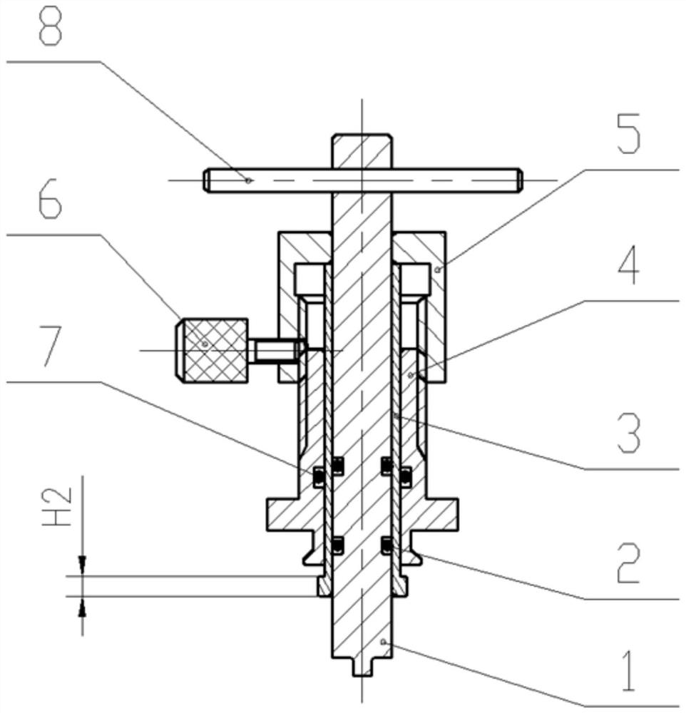
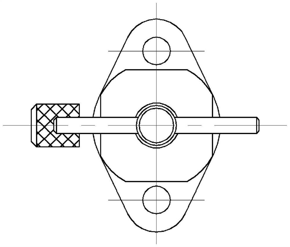
The invention belongs to the field of test tooling for aero-engine control accessories. The invention relates to an aero-engine speed limiter critical speed adjustment test device and method; the device comprises: a wrench, a mandrel, a base, an adjusting nut, and a set screw; the wrench is cylindrical, and the length is consistent with the outer diameter of the head of the mandrel; The rod is a cylindrical sleeve structure, and the head has a step; the end face of the head is provided with a groove, and the width of the groove matches the raised width of the wrench; the base and the adjusting nut are of sleeve structure, and the wrench is installed inside the ejector rod , the ejector rod is installed inside the base, and the adjusting nut is installed outside the base; the ejector rod is clearance fit with the wrench and the base respectively; there is an internal thread matching with the base; the set screw is installed on the adjusting nut, and the adjustment The nut locks with the base. The method of the device realizes the simultaneous online adjustment of the over-rotation speed and the speed-measurement speed adjustment test, which improves the work efficiency and ensures the qualification rate of the first-time installation of the product end cover assembly.

Description

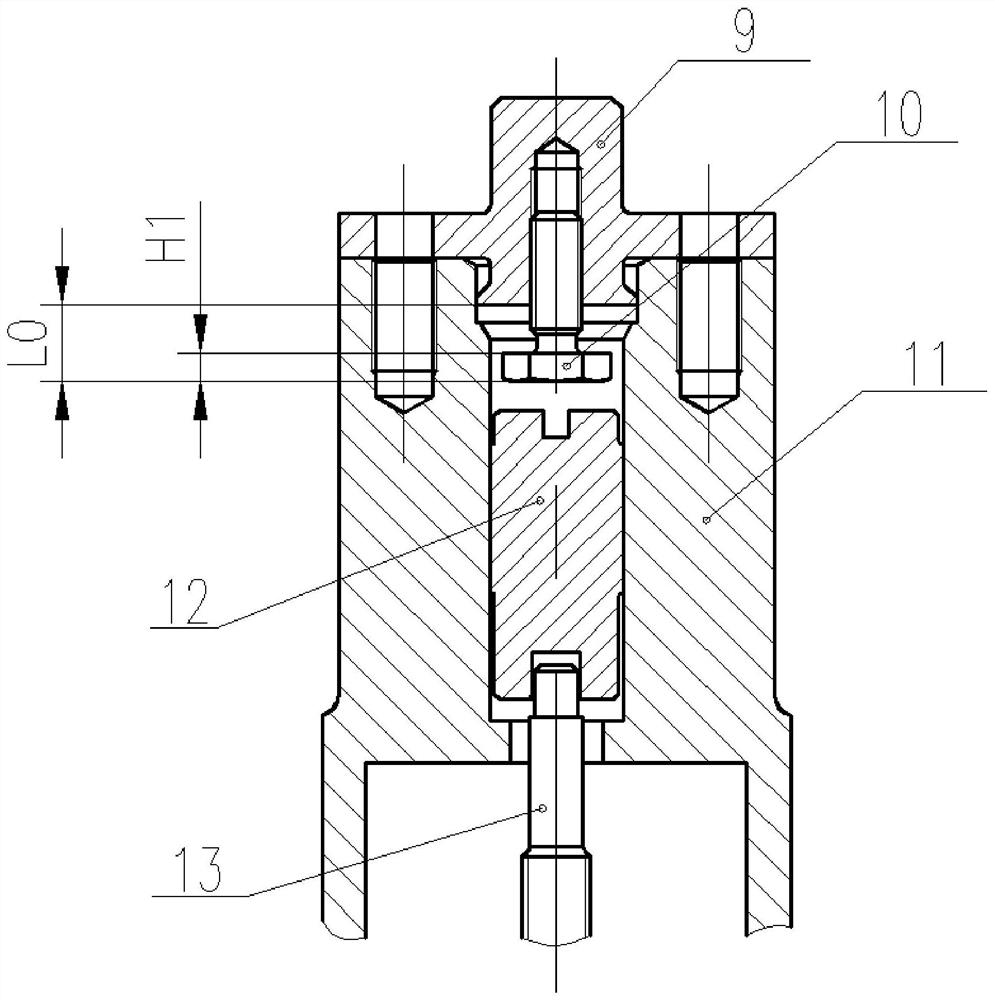
technical field [0001] The invention belongs to the field of aero-engine control accessory test tooling structure design, relates to an independent online adjustment structure design for simultaneously realizing the over-rotation speed limiter over-rotation speed and the tachometer speed, in particular to an aero-engine speed limiter critical speed adjustment test device and method. Background technique [0002] The core function of the aero-engine over-speed limiter is mainly realized by the mechanical centrifugal speed sensitive element, and the critical speed adjustment is the key to ensure the functional performance of the mechanical centrifugal speed sensitive element. The over-rotation limiter is a component of the turboprop propeller control system and is used to ensure that the propeller works stably under the limit speed. like figure 1 As shown, it includes: an adjuster 13, an adjusting screw 10, a piston 12, an end cover assembly 9, and a housing assembly 11; the ...

Claims


Application Information

Patent Timeline
Patent Type & Authority Patents(China)
IPC IPC(8): G01M15/00G01M13/00
CPCG01M15/00G01M13/00
Inventor 王辉胡守信刘雪娇
Owner BEIJING HANGKE ENGINE CONTROL SYST SCI & TECH
Why Eureka
Try Eureka