Microstrip power divider

A microstrip power divider and feeder technology, which is applied to waveguide-type devices, radiating element structures, electrical components, etc., can solve the problems of difficult to achieve gain difference, complex structure of microstrip power dividers, etc. Small footprint and the effect of gain difference

Pending Publication Date: 2020-10-13
SHENZHEN LONGHORN AUTOMOTIVE ELECTRONICS EQUIPCO
View PDF0 Cites 0 Cited by
  • Summary
  • Abstract
  • Description
  • Claims
  • Application Information

AI Technical Summary

Problems solved by technology

However, the structure of the existing microstrip power divider is relatively

Method used


Image

  • Microstrip power divider
  • Microstrip power divider

Examples


Embodiment Construction

[0017] The present application will be described in further detail below in conjunction with the accompanying drawings and specific embodiments. It should be understood that the following exemplary embodiments and descriptions are only used to explain the present invention, not as a limitation to the present invention, and, in the case of no conflict, the embodiments in the application and the features in the embodiments can be combined with each other .

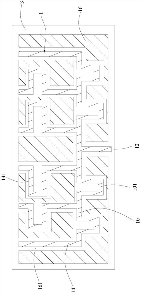
[0018] Such as figure 1 As shown, the embodiment of the present invention provides an embodiment to provide a microstrip power splitter 1, which is arranged on the front of the dielectric substrate 3, and includes a main feeder 10 and an input end 12 and a multiplex output end 14 arranged on the main feeder 10, The input end 12 is formed by extending from the midpoint of the main feeder 10 to one side, and the multiple output ends 14 are symmetrically arranged on both sides of the input end 12 and respectively from the main...


PUM


Abstract

The embodiment of the invention provides a microstrip power divider. The microstrip power divider is arranged on the front surface of a dielectric substrate. The microstrip power divider comprises a main feeder line, an input end and a plurality of output ends, wherein the input end and the plurality of output ends are arranged on the main feeder line; the input end is formed by extending from themidpoint of the main feeder line to one side; the multiple paths of output ends are symmetrically arranged on the two sides of the input end and are formed by extending from the midpoint of the mainfeeder line to predetermined connecting points distributed along the two tail ends of the main feeder line in the direction opposite to the extending direction of the input end; the positions and theshapes of the output ends arranged on the two sides of the input end are symmetrically set relative to the input endl; and the amplitudes and the phases of the output ends are gradually decreased fromthe middle of the main feeder line to the two tail ends in a cosecant square forming mode. According to the embodiments of the invention, the amplitudes and phases of the output ends are weighted step by step from one tail end to the other tail end of the main feeder line in a quasi-cosecant square forming mode, current and phase weighting of all the output ends is achieved, beam forming can be effectively achieved, and a preset gain difference value can be effectively achieved.

Description

technical field [0001] Embodiments of the present invention relate to the technical field of microstrip array antennas, in particular to a microstrip power splitter. Background technique [0002] Existing microstrip array antennas usually include a dielectric substrate, a microstrip power splitter and a plurality of radiation line arrays that are arranged on the front of the dielectric substrate, and each output end of the microstrip power splitter is connected to a radiation line array and feeds the connected radiating array. Among them, the vehicle-mounted microstrip array antenna in the 24GHz frequency band needs to be shaped on the antenna pattern to expand the detection range of the antenna in order to realize lane change assistance and blind spot monitoring. Generally, two beams for long-distance and short-distance detection are required within the antenna forming range, and the gain difference between the two beams is 6dB. However, the structure of the existing micr...

Claims


Application Information

Patent Timeline
IPC IPC(8): H01Q21/00H01Q1/50H01Q1/38H01Q21/06H01Q21/12H01P5/12
CPCH01P5/12H01Q1/38H01Q1/50H01Q21/0075H01Q21/061H01Q21/12
Inventor 罗小平曾峰袁海平
Owner SHENZHEN LONGHORN AUTOMOTIVE ELECTRONICS EQUIPCO
Why Eureka
Try Eureka