Thin-substrate phase amplitude correction oscillator difference beam planar horn antenna

A horn antenna and amplitude correction technology, applied in waveguide horn, radiating element structure, circuit and other directions, can solve the problems of low gain of horn antenna, zero depth of difference beam antenna, radiation directivity and gain reduction, etc. The effect of inconsistent amplitude, small feed loss and compact structure

Inactive Publication Date: 2014-02-26
SOUTHEAST UNIV
View PDF3 Cites 0 Cited by
  • Summary
  • Abstract
  • Description
  • Claims
  • Application Information

AI Technical Summary

Problems solved by technology

In addition, the gain of the traditional substrate-integrated waveguide planar horn antenna is relatively low. The reason is that due to the continuous opening of the horn mouth, the phase is not synchronized when the electromagnetic wave propagates to the horn aperture surface, and the amplitude distribution of the aperture electric field intensity is not uniform. The radiation directivity and gain are reduced, making the zero depth of the formed differential beam antenna shallower and the slope lower, which affects the direction finding accuracy of the radar
At present, methods such as dielectric loading and dielectric prisms have been used to correct the horn aperture field, but these methods can only improve the consistency of the phase distribution, but cannot improve the uniformity of the amplitude distribution, and these phase calibration structures increase the overall structural size of the antenna

Method used


Image

  • Thin-substrate phase amplitude correction oscillator difference beam planar horn antenna

Examples


Embodiment Construction

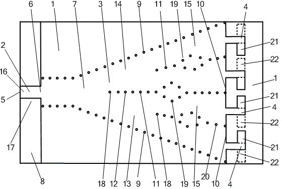
[0026] The implementation adopted by the present invention is: a thin substrate phase amplitude correction element difference beam planar horn antenna includes a microstrip feeder 2, a substrate integrated horn antenna 3, and a plurality of elements 4 arranged on a dielectric substrate 1. The microstrip The first port 5 of the feeder 2 is the input and output port of the antenna, and the second port 6 of the microstrip feeder 2 is connected to the substrate integrated horn antenna 3; the substrate integrated horn antenna 3 is composed of a first metal located on one side of the dielectric substrate 1. The plane 7, the second metal plane 8 located on the other side of the dielectric substrate 1 and the two rows of metalized via horn side walls 9 connecting the first metal plane 7 and the second metal plane 8 through the dielectric substrate 1, the substrate integrates the horn The width between the two rows of metalized via-hole horn side walls 9 of the antenna 3 gradually become...


PUM


Abstract

The invention discloses a thin-substrate phase amplitude correction oscillator difference beam planar horn antenna, and relates to a horn antenna. The thin-substrate phase amplitude correction oscillator difference beam planar horn antenna comprises a micro-strip feeder (2), a horn antenna body (3) and oscillators (4), wherein the micro-strip feeder (2), the horn antenna body (3) and the oscillators (4) are arranged on a dielectric substrate (1), the horn antenna body (3) comprises a first metal plane (7), a second metal plane (8) and two metallization through hole horn side walls (9), the horn antenna body (3) is provided with an odd number of metallization through hole arrays (11), and an even number of dielectric-loaded waveguides (15), on an aperture surface (10) of the horn antenna body (3), the widths of the dielectric-loaded waveguides (15) are equal, each dielectric-loaded waveguide (15) is connected with the corresponding oscillator (4), a left-half antenna (13) and a right-half antenna (14) are arranged symmetrically, and the oscillators (4) connected with the left-half antenna (13) and the oscillators (4) connected with the right-half antenna (14) are arranged symmetrically. Electromagnetic waves can reach the oscillators in an equal-amplitude and in-phase mode and then carry out radiation, and the direction of polarization of a radiation field is parallel to the dielectric substrate; the thin-substrate phase amplitude correction oscillator difference beam planar horn antenna can be manufactured with the thin substrate, and is high in gain, large in zero drawdown, low in cost and compact in structure.

Description

technical field [0001] The invention relates to a horn antenna, in particular to a planar horn antenna with a thin substrate phase amplitude correction dipole difference beam. Background technique [0002] Horn antennas are widely used in systems such as satellite communications, ground microwave links, and radio telescopes. However, the huge geometric size of the three-dimensional horn antenna restricts its application and development in planar circuits. In recent years, the proposal and development of substrate-integrated waveguide technology have greatly promoted the development of planar horn antennas. The substrate-integrated waveguide has the advantages of small size, light weight, easy integration and fabrication. The planar substrate-integrated waveguide horn antenna based on the planar substrate-integrated waveguide not only has the characteristics of the horn antenna, but also realizes the miniaturization and light weight of the horn antenna, and is easy to int...

Claims


Application Information

Patent Timeline
Patent Type & Authority Applications(China)
IPC IPC(8): H01Q13/02H01Q1/38
Inventor 殷晓星赵洪新苑婷婷
Owner SOUTHEAST UNIV
Why Eureka
Try Eureka