Discrete Domain Current Loop Two Degrees of Freedom Control Method for Permanent Magnet Synchronous Motor

A technology of permanent magnet synchronous motor and control method, which is applied in the direction of motor generator control, electronic commutation motor control, control system, etc., and can solve problems such as control performance disturbance, discrete error highlighting, and control bandwidth restriction, so as to ensure the parameters Robustness, the effect of increasing the stable region

Active Publication Date: 2021-08-10
HEFEI UNIV OF TECH
View PDF5 Cites 0 Cited by
  • Summary
  • Abstract
  • Description
  • Claims
  • Application Information

AI Technical Summary

Problems solved by technology

However, the current commonly used current controllers will have the following problems when facing the high-speed and low-carrier ratio operation state: 1) The cross-coupling disturbance term introduced by the rotation coordinate transformation between the d and q-axis subsystems increases with the increase of the operating speed However, the increase in height even becomes the main determinant factor of the d and q axis current components, which brings great disturbance to the control performance of the d and q axis subsystems; 2) limited by the allowable switching frequency and heat dissipation conditions of power devices, the corresponding The carrier ratio is low, which makes the discretization error prominent, the influence of sampling and control delay is aggravated, and even leads to system instability in severe cases
[0008] 1. The uneven air gap of the built-in permanent magnet synchronous motor makes the AC and direct axis inductance unequal, and the complex vector technology cannot be used to simplify the permanent magnet motor voltage model into a single-input single-output model. Based on the single-input and single-output control object described by the vector, the discrete domain design scheme of the current controller is not suitable for the built-in permanent magnet synchronous motor;
[0009] 2. The design of the discrete domain current controller for the built-in permanent magnet synchronous motor reported in reference 3 has the problem that the current loop following performance and the anti-disturbance performance cannot be taken into account at the same time, and the parameter deviation seriously restricts the allowable control in actual use. Bandwidth, insufficient robustness of system parameters

Method used


Image

  • Discrete Domain Current Loop Two Degrees of Freedom Control Method for Permanent Magnet Synchronous Motor
  • Discrete Domain Current Loop Two Degrees of Freedom Control Method for Permanent Magnet Synchronous Motor
  • Discrete Domain Current Loop Two Degrees of Freedom Control Method for Permanent Magnet Synchronous Motor

Examples


Embodiment Construction

[0064] In the following, the two-degree-of-freedom control method of the discrete domain current loop of the permanent magnet synchronous motor according to the present invention will be described in detail in conjunction with the accompanying drawings and embodiments.

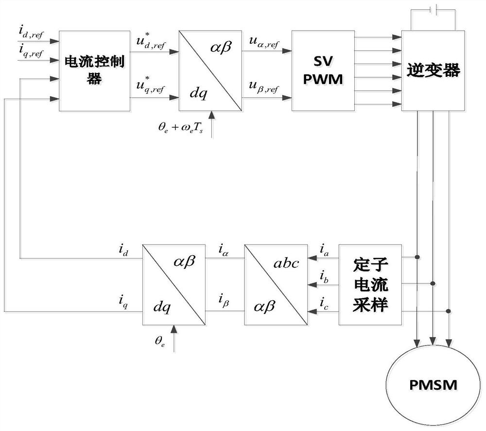
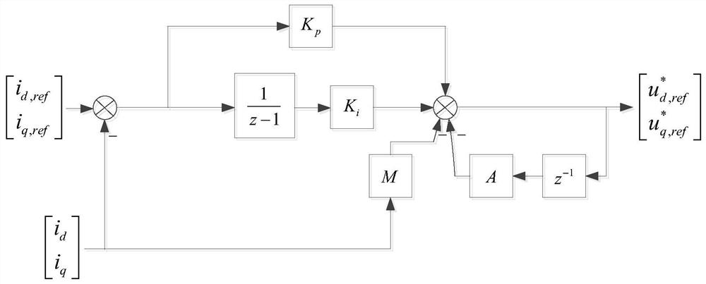
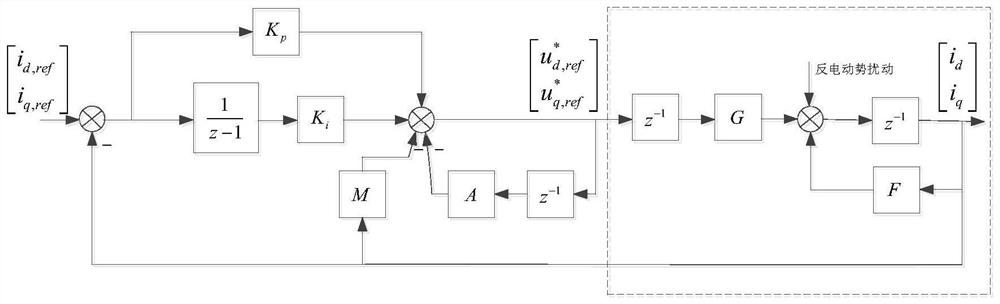
[0065] figure 1 It is the control block diagram of the permanent magnet synchronous motor current loop control system in the present invention, figure 2 It is a structural block diagram of a permanent magnet synchronous motor current controller in the present invention, image 3 It is an equivalent structural block diagram of the permanent magnet synchronous motor current loop control system in the rotating dq coordinate system in the present invention. Depend on figure 1 , figure 2 and image 3 Visible, the present invention comprises the following steps:

[0066] Step 1, collect the rotor electrical angular velocity ω of the permanent magnet synchronous motor e and rotor electrical angle θ e , colle...


PUM


Abstract

The invention relates to the field of permanent magnet synchronous motor control, in particular to a two-degree-of-freedom control method for a discrete domain current loop of a permanent magnet synchronous motor. In this method, the current controller is designed through the coefficient matrix F and the input matrix G of the discrete domain mathematical model of the permanent magnet synchronous motor in the rotating dq coordinate system, and the angle lag problem caused by the one-beat delay of the compensation digital control is considered. The present invention makes the current loop following design of the permanent magnet synchronous motor not restricted by the anti-disturbance performance, and the introduction of additional parameter degrees of freedom can realize the active configuration of the anti-disturbance performance, and at the same time better overcome the current tracking of the permanent magnet synchronous motor The contradiction between rapidity and parameter robustness, while obtaining fast or minimum beat current response, greatly improves the parameter robustness of the system, thereby improving the operating quality of the permanent magnet synchronous motor current control system.

Description

technical field [0001] The invention relates to the field of permanent magnet synchronous motor control, in particular to a two-degree-of-freedom control method for a discrete domain current loop of a permanent magnet synchronous motor. Background technique [0002] Permanent magnet synchronous motors are widely used in high-performance drive applications such as new energy vehicles and industrial servo systems due to their high efficiency, high power density, specific power, and high starting torque. For many years, the proportional-integral (PI) controller based on the rotor field-oriented synchronous rotating coordinate system has been the industry standard for AC motor current control because of its wide speed range and zero steady-state error. However, the current commonly used current controllers will have the following problems when facing the high-speed and low-carrier ratio operation state: 1) The cross-coupling disturbance term introduced by the rotation coordinate...

Claims


Application Information

Patent Timeline
Patent Type & Authority Patents(China)
IPC IPC(8): H02P21/22H02P21/00
CPCH02P21/0003H02P21/22
Inventor 杨淑英王奇帅谢震张兴
Owner HEFEI UNIV OF TECH
Why Eureka
Try Eureka