Cuff type sphygmomanometer

A sphygmomanometer and cuff technology, applied in vascular assessment, cardiac catheterization, etc., can solve problems such as button fastener damage, unusable sphygmomanometer, and taking up a lot of time.

Pending Publication Date: 2020-10-16
合捷联创(北京)科技有限公司
View PDF0 Cites 1 Cited by
  • Summary
  • Abstract
  • Description
  • Claims
  • Application Information

AI Technical Summary

Problems solved by technology

[0003] 1. Inconvenient to disassemble
[0004] The existing sphygmomanometer cuff and sphygmomanometer adopt the button fastener method, which is inconvenient to disassemble
[0005] 2. Button fasteners are easily damaged
[0006] The cuff and the sphygmomanometer are connected by button fasteners. The button fasteners are made of hard plastic. It takes a lot of force to remove them. Frequent disassembly will cause damage to the button fasteners and make the sphygmomanometer unusable.
[0007] 3. The cost of replacing the cuff is high
[0008] It takes a lot of time to replace the cuff, which greatly increases labor costs
[0009] 4. It takes a long time to clean the cuff
[0010] The sphygmomanometer needs to wait for the cuff to be cleaned before it can be used, which reduces the efficiency of the sphygmomanometer
[0011] 5. The cuff is not easy to clean
[0012] It is easy to produce odor due to the accumulation of sweat, and cause the growth of bacteria and viruses
[0013] 6. The cuff is easily damaged
[0014] Because the sphygmomanometer and the cuff are directly connected by the fastener structure, the detachable type is easy to damage the cuff, making the sphygmomanometer unusable

Method used


Image

  • Cuff type sphygmomanometer
  • Cuff type sphygmomanometer
  • Cuff type sphygmomanometer

Examples


Embodiment Construction

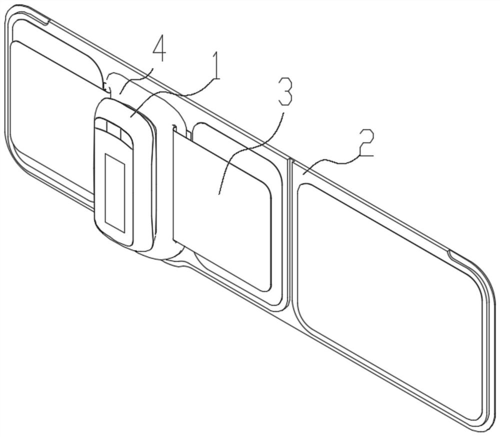
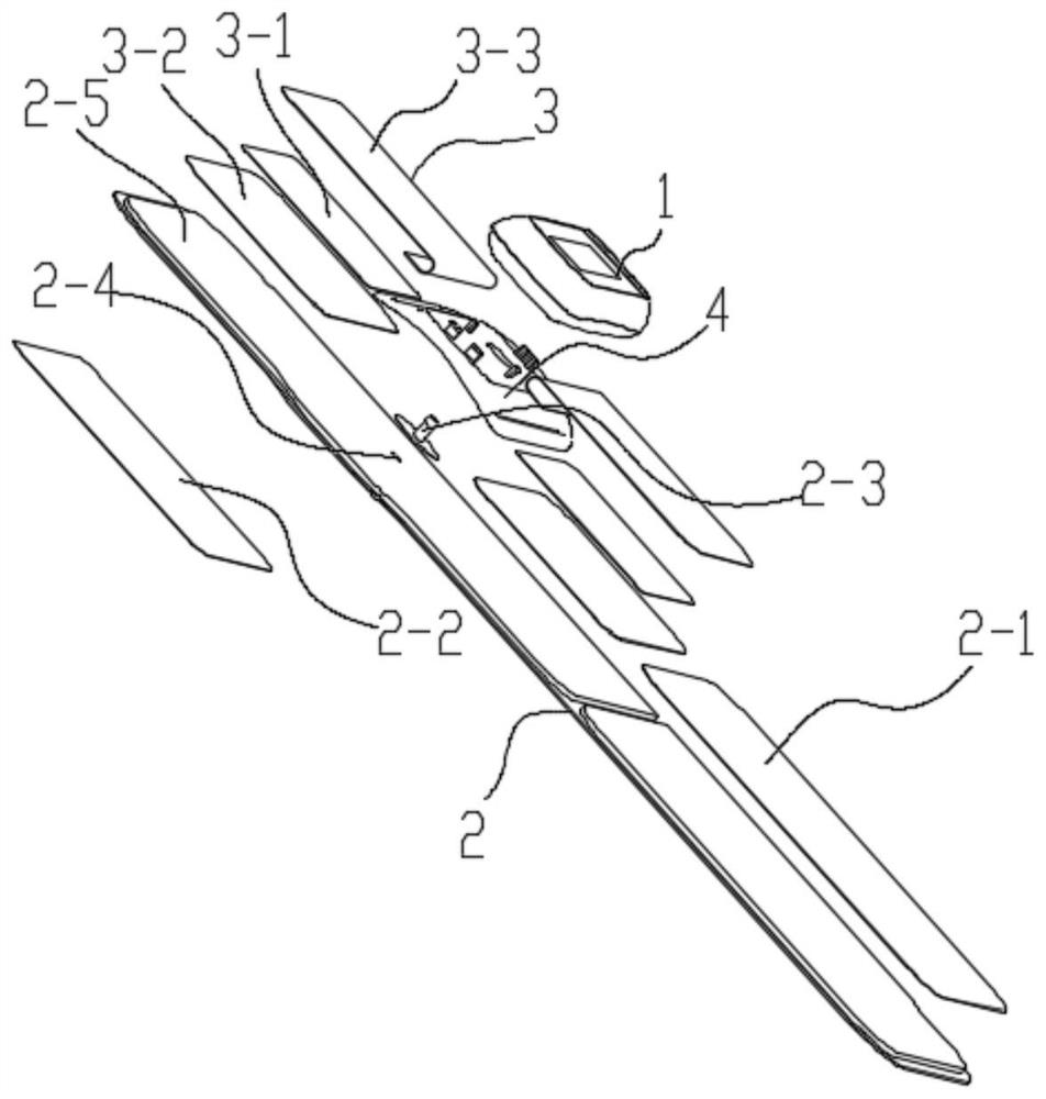
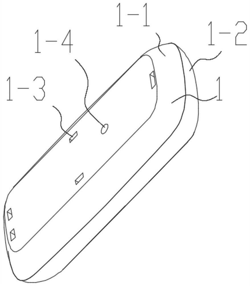
[0266] Such as Figure 1 to Figure 23 As shown, this embodiment provides a cuff-type sphygmomanometer, including a sphygmomanometer 1 and a cuff 2, and the sphygmomanometer 1 and the cuff 2 are detachably connected by a belt-type detachable connecting part 3 .

[0267] Various improvements of this embodiment are described in detail below.

[0268] Such as Figure 21 to Figure 22 As shown, the detachable connection between the sphygmomanometer 1 and the cuff 2 through the belt-type detachable connecting part 3 is directly through the belt-type detachable connection between the sphygmomanometer 1 and the cuff 2 The connection part 3 is detachably connected.

[0269] Of course, it can also befigure 1 As shown, the detachable connection between the sphygmomanometer 1 and the cuff 2 through the belt-type detachable connecting part 3 is that the detachable connection between the sphygmomanometer 1 and the cuff 2 is indirectly through the belt-type detachable The connection part ...


PUM


Abstract

The invention discloses a cuff type sphygmomanometer. The sphygmomanometer comprises a sphygmomanometer body and a cuff, and the sphygmomanometer body and the cuff are detachably connected through a strap type detachable connecting component. The sphygmomanometer and the cuff are detachably connected through the strap type detachable connecting component, which means that: the sphygmomanometer andthe cuff are directly and detachably connected through the strap type detachable connecting component, or the sphygmomanometer and the cuff are indirectly and detachably connected through the strap type detachable connecting component. The sphygmomanometer and the cuff are indirectly and detachably connected through the strap type detachable connecting component, which means that a clamping plateis arranged between the strap type detachable connecting component and the sphygmomanometer. According to the cuff type sphygmomanometer, the cuff and the sphygmomanometer can be easily separated with small force, disassembly is convenient, the strap type detachable connecting component is not prone to damage, the cuff replacement cost is greatly reduced, the cuff cleaning time is short, the cuffis easy to clean, and the cuff is not prone to damage.

Description

technical field [0001] The invention relates to a medical appliance, in particular to a cuff type sphygmomanometer. Background technique [0002] In the cuff-type sphygmomanometer of the prior art, the cuff and the sphygmomanometer are usually connected in one piece, or the connection is formed by button fasteners, and the sphygmomanometer and the cuff are directly connected by 6-8 button-type structures. Forcibly disassemble with external force. Such cuff-type sphygmomanometers have the following disadvantages. [0003] 1. Inconvenient to disassemble [0004] The existing sphygmomanometer cuff and sphygmomanometer adopt the button fastening method, which is inconvenient to disassemble. [0005] 2. Button fasteners are easily damaged [0006] The cuff and the sphygmomanometer are connected by button fasteners. The button fasteners are made of hard plastic. It takes a lot of force to remove them. Frequent disassembly will cause damage to the button fasteners and make the ...

Claims


Application Information

Patent Timeline
Patent Type & Authority Applications(China)
IPC IPC(8): A61B5/022
CPCA61B5/02141A61B5/022A61B5/02233
Inventor 田鲲
Owner 合捷联创(北京)科技有限公司
Why Eureka
Try Eureka