Wearable automatic eye drop instillator

A drip injector and eyedrop technology, applied in the field of medical devices, can solve problems such as single way of dispensing medicine, easy positioning and inaccurate positioning, and failure to meet the actual needs of different patients, achieving accurate positioning and solving the effects of easy forgetting

Active Publication Date: 2020-10-16
PEKING UNIV THIRD HOSPITAL
View PDF15 Cites 1 Cited by
  • Summary
  • Abstract
  • Description
  • Claims
  • Application Information

AI Technical Summary

Problems solved by technology

[0006] The problems existing in the above-mentioned automatic eye drop device in the prior art are that it is easy to be inaccurate in positioning, and the method of dispensing medicine is single, which cannot meet the actual needs of different patients.

Method used


Image

  • Wearable automatic eye drop instillator
  • Wearable automatic eye drop instillator

Examples


no. 1 example

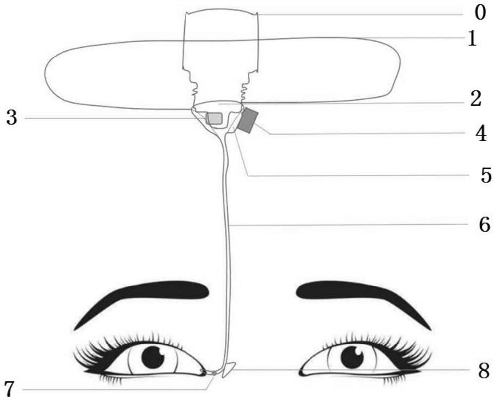
[0026] Such as figure 1 As shown, the wearable automatic eyedrop injector of the present invention includes an upper fixing device 1, a medicine bottle connector 2, a chip 3, a power system 4, an air bag 5, a drug delivery pipeline 6, a valve 7 and a lower fixing device 8 , the upper end fixing device is used to fix the medicine bottle O; eye drops are contained in the medicine bottle; the upper part of the medicine bottle connector 2 is airtightly connected with the outlet of the medicine bottle O; the medicine bottle connector The lower part of 2 communicates with the liquid inlet end of the drug delivery pipeline 6; the airbag 5 is arranged between the outlet of the medicine bottle and the medicine bottle connector; the chip 3 is communicated with the power system 4, and the chip 3 is used for Control the action of the power system 4; the power system 4 is connected with the air bag 5, and the power system 4 is used to control the entry and exit of eye medicine by changing ...

no. 2 example

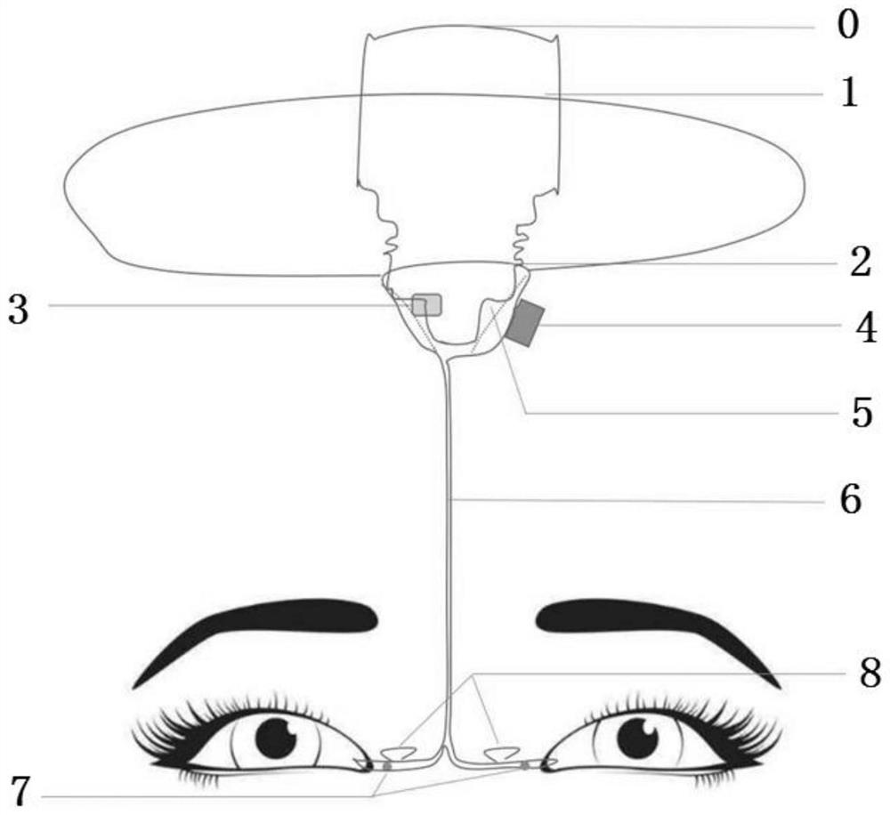
[0039] Such as figure 2 As shown, as an optional embodiment, in the wearable automatic eyedrop injector of the present invention, the liquid outlet end of the drug delivery pipeline 6 has two outlets, and each outlet is aimed at one of the patients. Eye drops can be administered to both eyes of the patient at the same time. figure 2 Other components in the second embodiment shown are completely the same as those in the first embodiment, and will not be repeated here.

[0040] In addition to the above-mentioned first embodiment and second embodiment, those skilled in the art can fully understand that, as a further preferred embodiment, the wearable automatic eyedrop injector of the present invention can use the above-mentioned upper end fixing device Hold one or more vials above the patient's eyes. Multiple vials can hold different eye medications. For different eye drops that will not affect each other, multiple medicine bottles can be connected to the same medicine deliv...


PUM


Abstract

The invention discloses a wearable automatic eye drop instillator. The wearable automatic eye drop instillator comprises an upper end fixing device, a medicine bottle connector, a chip, a power system, an air bag, a medicine conveying pipeline, a valve and a lower end fixing device, wherein the upper end fixing device is used for fixing a medicine bottle; the upper part of the medicine bottle connector is airtightly connected with an outlet of the medicine bottle; the lower part of the medicine bottle connector communicates with the liquid inlet end of the medicine conveying pipeline; the airbag is arranged between the outlet of the medicine bottle and the medicine bottle connector; the chip is in communication connection with the power system and is used for controlling actions of the power system; the power system is connected with the air bag and is used for controlling feeding and discharging of eye drops by changing the size of the air bag; the valve is arranged on the medicine conveying pipeline and is used for controlling opening and closing of the medicine conveying pipeline; and the lower end fixing device is used for fixing the liquid outlet end of the medicine conveyingpipeline beside the eyes of a patient and enabling an outlet in the liquid outlet end of the medicine conveying pipeline to be aligned with a medicine applying part of the eyes of the patient.

Description

technical field [0001] The invention relates to the technical field of medical devices, in particular to a wearable automatic eye drops injector. Background technique [0002] Eye drops are an effective means of treating eye diseases. Eye drops can effectively treat eye diseases and relieve clinical symptoms by instilling eye drops into the eyes, and have been widely used in clinical practice. [0003] In the prior art, the instillation of eye drops usually requires the patient or the medical staff to hold the eye drop bottle to instill the eye drops in the eyes of the patient. For people who need long-term medication and frequent medication, they need to stop the work at hand, which affects Normal life and work, and easy to forget. For the elderly, especially those with impaired mobility, such as Parkinson's patients, it is very difficult to accurately inject the medicine into the eye, which not only wastes the medicine but also affects the therapeutic effect. [0004] A ...

Claims


Application Information

Patent Timeline
Patent Type & Authority Applications(China)
IPC IPC(8): A61F9/00G08C17/02H04M1/725
CPCA61F9/0008G08C17/02
Inventor 彭荣梅洪晶
Owner PEKING UNIV THIRD HOSPITAL
Why Eureka
Try Eureka