Vacuum freeze drying type solid-liquid separation method
A technology of vacuum freeze-drying and solid-liquid separation, applied in separation methods, chemical instruments and methods, sublimation, etc., can solve the problems of low automation, poor safety, and poor accuracy, and achieve high automation, good airtightness, and safety The effect of high coefficient
- Summary
- Abstract
- Description
- Claims
- Application Information
AI Technical Summary
Problems solved by technology
Method used
Image

Examples
Embodiment 1
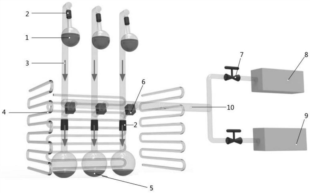
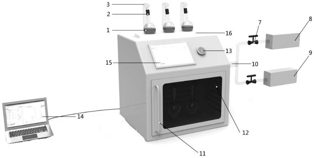
[0024] A method for vacuum freeze-drying solid-liquid separation, adopting vacuum freeze-drying solid-liquid separation device to carry out solid-liquid separation, said device (such as figure 1 , figure 2 Shown) comprises separation area, cold trap, vacuum system, steam generator, and described separation area comprises lyophilization bottle, channel, collection bottle, channel is used for connecting lyophilization bottle and collection bottle, is provided with vacuum system and collection bottle on the channel The pipeline connected to the steam generator, the receiving bottle is placed in the cold trap, the freeze-dried bottle is placed on the upper surface of the top of the cold trap, the condensation tube is coiled in the cold trap, the separation area, cold trap, vacuum system, steam generator and related control equipment It is connected with the control software workstation; when performing solid-liquid separation, it includes the following steps: (1) Place the solid-...
Embodiment 2
[0045] A device for vacuum freeze-drying solid-liquid separation, said device (such as figure 1 , figure 2 Shown) comprises separation area, cold trap, vacuum system, steam generator, and described separation area comprises lyophilization bottle, channel, collection bottle, channel is used for connecting lyophilization bottle and collection bottle, is provided with vacuum system and collection bottle on the channel The pipeline connected to the steam generator, the receiving bottle is placed in the cold trap, the freeze-dried bottle is placed on the upper surface of the top of the cold trap, the condensation tube is coiled in the cold trap, the separation area, cold trap, vacuum system, steam generator and related control equipment It is connected with the control software workstation; when performing solid-liquid separation, it includes the following steps: (1) Put 1L of sulfur-containing sludge leaching suspension (solid-liquid ratio is 1:10) into a freeze-dried bottle and ...
Embodiment 3
[0066] A device for vacuum freeze-drying solid-liquid separation, said device (such as figure 1 , figure 2 Shown) comprises separation area, cold trap, vacuum system, steam generator, and described separation area comprises lyophilization bottle, channel, collection bottle, channel is used for connecting lyophilization bottle and collection bottle, is provided with vacuum system and collection bottle on the channel The pipeline connected to the steam generator, the receiving bottle is placed in the cold trap, the freeze-dried bottle is placed on the upper surface of the top of the cold trap, the condensation tube is coiled in the cold trap, the separation area, cold trap, vacuum system, steam generator and related control equipment It is connected with the control software workstation; when performing solid-liquid separation, it includes the following steps: (1) 1L of waste hydrochloric acid leach solution (solid-liquid ratio is 1:10, the main component of waste salt is sodiu...
PUM
 Abstract
Description
Claims
Application Information
 - R&D Engineer
- R&D Manager
- IP Professional
- Industry Leading Data Capabilities
- Powerful AI technology
- Patent DNA Extraction
Browse by: Latest US Patents, China's latest patents, Technical Efficacy Thesaurus, Application Domain, Technology Topic.
© 2024 PatSnap. All rights reserved.Legal|Privacy policy|Modern Slavery Act Transparency Statement|Sitemap