
A fool-proof mechanism for automatic feeding vibration plate of electronic components

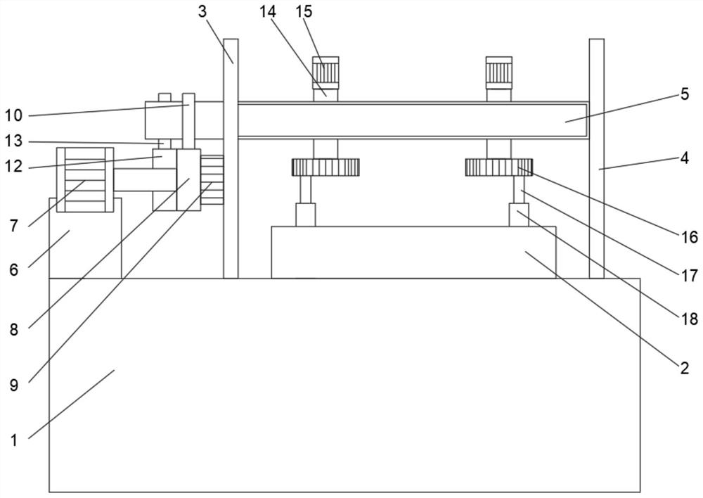
A technology of automatic feeding and electronic components, applied in the direction of vibrating conveyors, conveyors, conveyor objects, etc., can solve the problems of waste of manpower, low efficiency of vibrating plate feeding, difficult operation, etc., to improve processing efficiency and novel structure Flexibility and the effect of improving cleaning efficiency

Active Publication Date: 2021-06-29
YANCHENG BOSHI ELECTRONICS CO LTD
View PDF0 Cites 0 Cited by
  • Summary
  • Abstract
  • Description
  • Claims
  • Application Information

AI Technical Summary

Problems solved by technology

[0003] During the working process of the existing vibrating plate for feeding electronic components, the electronic components deviate when vibrating, causing the vibrating plate to be stuck and unable to continue feeding. Manual cleaning is required to continue automatic feeding. The structure is complex and the operation is difficult. , wasting a lot of manpower, which greatly reduces the processing efficiency of electronic components. The traditional automatic feeding vibrating plate, when the fool-proof mechanism works, most of the vibrating plate is in an inoperable state, making the feeding efficiency of the vibrating plate very low.

Method used


Image

  • A fool-proof mechanism for automatic feeding vibration plate of electronic components
  • A fool-proof mechanism for automatic feeding vibration plate of electronic components
  • A fool-proof mechanism for automatic feeding vibration plate of electronic components

Examples


Embodiment Construction

[0026] The following will clearly and completely describe the technical solutions in the embodiments of the present invention with reference to the accompanying drawings in the embodiments of the present invention. Obviously, the described embodiments are only some, not all, embodiments of the present invention. Based on the embodiments of the present invention, all other embodiments obtained by persons of ordinary skill in the art without making creative efforts belong to the protection scope of the present invention.

[0027] In the description of the present invention, it should be noted that the terms "center", "upper", "lower", "left", "right", "vertical", "horizontal", "inner", "outer" etc. The indicated orientation or positional relationship is based on the orientation or positional relationship shown in the drawings, and is only for the convenience of describing the present invention and simplifying the description, rather than indicating or implying that the referred d...


PUM


Abstract

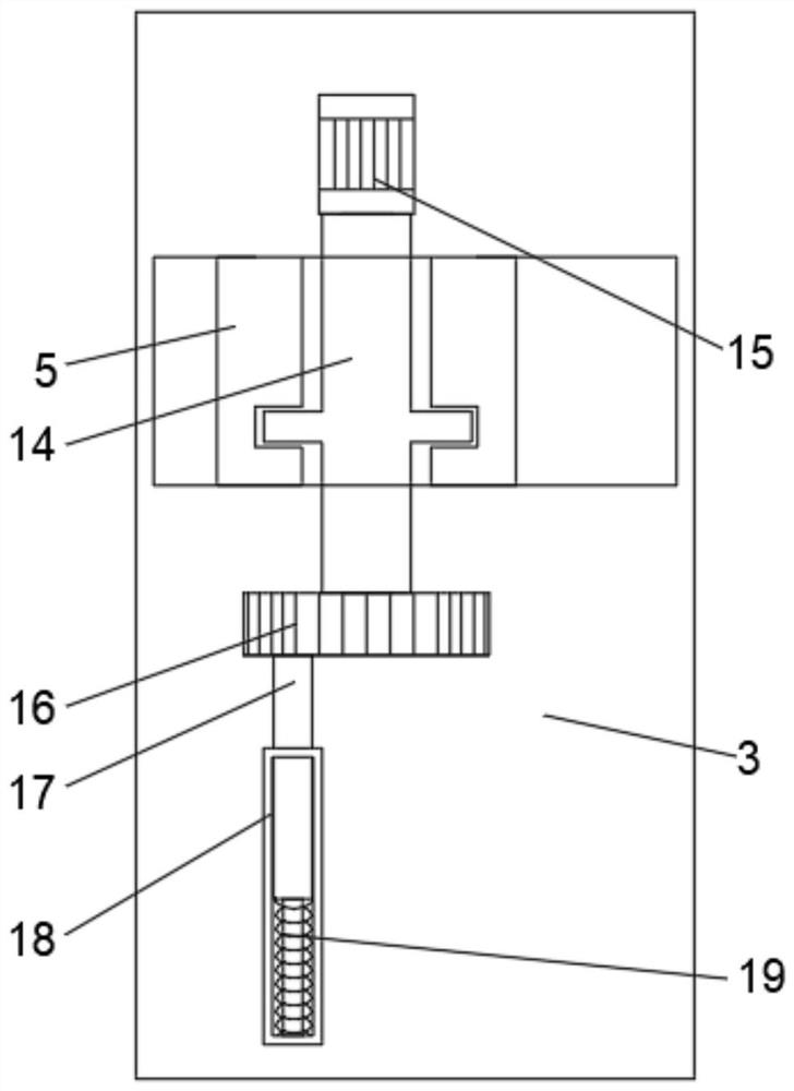
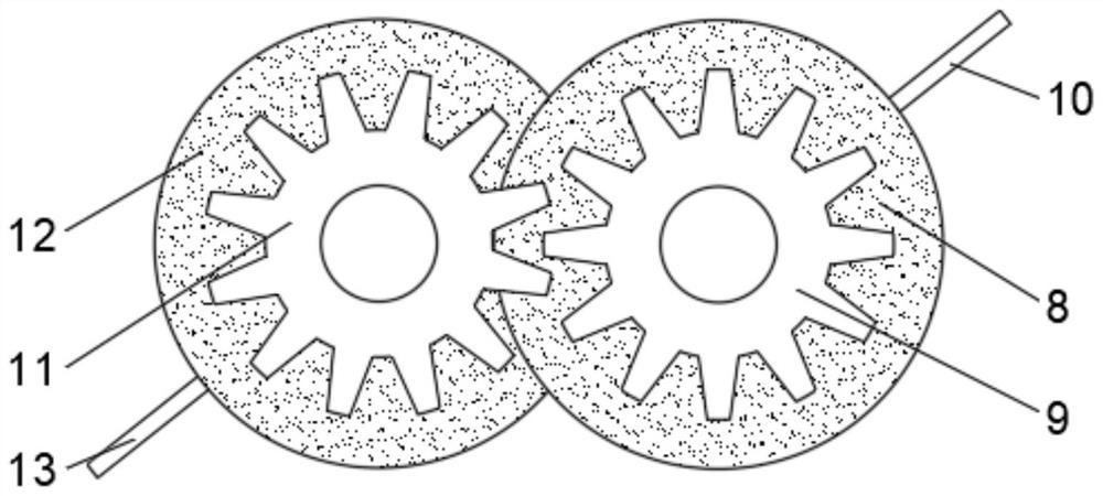
The invention discloses a vibrating plate anti-fooling mechanism for automatic feeding of electronic components. A chute is provided between the first partition and the second partition, a support base is fixedly connected to the top end of the base away from the second partition, and a first motor is fixedly connected to the top of the support base. A motor drive shaft is fixedly connected with the first runner and the first gear. The electronic component automatic feeding vibrating plate anti-fooling mechanism of the present invention is provided with a stirring rod, a second motor and a rotating wheel, and the stirring rod is driven by the second motor to rotate and stir in the feeding track on the top of the vibrating plate main body. Compared with the traditional Electronic components are automatically fed to the vibrating plate. This novel and flexible structure keeps the track of the vibrating plate of electronic components unimpeded, and does not require manual operation and maintenance. It is very convenient and improves the processing efficiency of electronic components.

Description

technical field [0001] The invention relates to the technical field of foolproof mechanism equipment, in particular to a foolproof mechanism for automatic feeding of electronic components to a vibrating plate. Background technique [0002] Fool-proof is a behavioral restraint method for prevention and correction. By using the restraint method to avoid mistakes, the operator can directly complete the correct operation without paying attention, experience and professional knowledge. In industrial design , In order to avoid the machine or personal injury caused by the user's operation error, there will be preventive measures for these possible situations, which are called fool-proofing. [0003] During the working process of the existing vibrating plate for feeding electronic components, the electronic components deviate when vibrating, causing the vibrating plate to be stuck and unable to continue feeding. Manual cleaning is required to continue automatic feeding. The structur...

Claims


Application Information

Patent Timeline
Patent Type & Authority Patents(China)
IPC IPC(8): B65G27/02B65G27/08B65G45/10
CPCB65G27/02B65G27/08B65G45/10
Inventor 袁敏
Owner YANCHENG BOSHI ELECTRONICS CO LTD
Learn More