Twisting device capable of uniformly twisting

A twisting device and uniform technology, applied in textiles and papermaking, etc., can solve the problems of insufficiently uniform twisting and inability to limit the position, and achieve the effect of avoiding entanglement and reducing wear and tear.

Active Publication Date: 2020-10-16
宿迁市正益纺织有限公司
View PDF5 Cites 2 Cited by
  • Summary
  • Abstract
  • Description
  • Claims
  • Application Information

AI Technical Summary

Problems solved by technology

[0003] The object of the present invention is to provide a twisting device with uniform twisting to solve the problem that t

Method used


Image

  • Twisting device capable of uniformly twisting
  • Twisting device capable of uniformly twisting
  • Twisting device capable of uniformly twisting

Examples


Embodiment 1

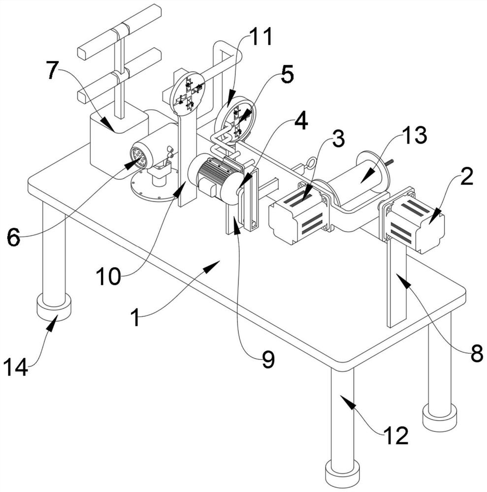
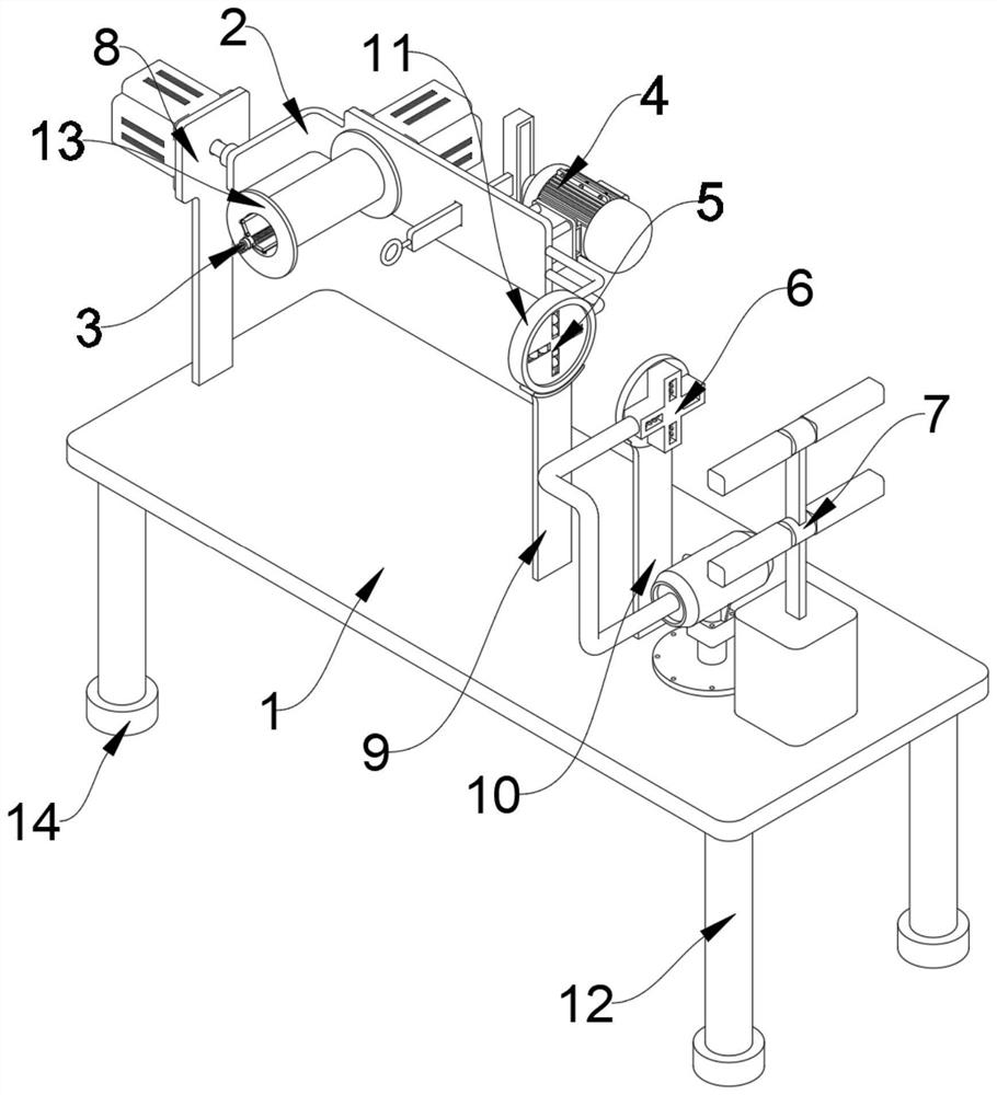
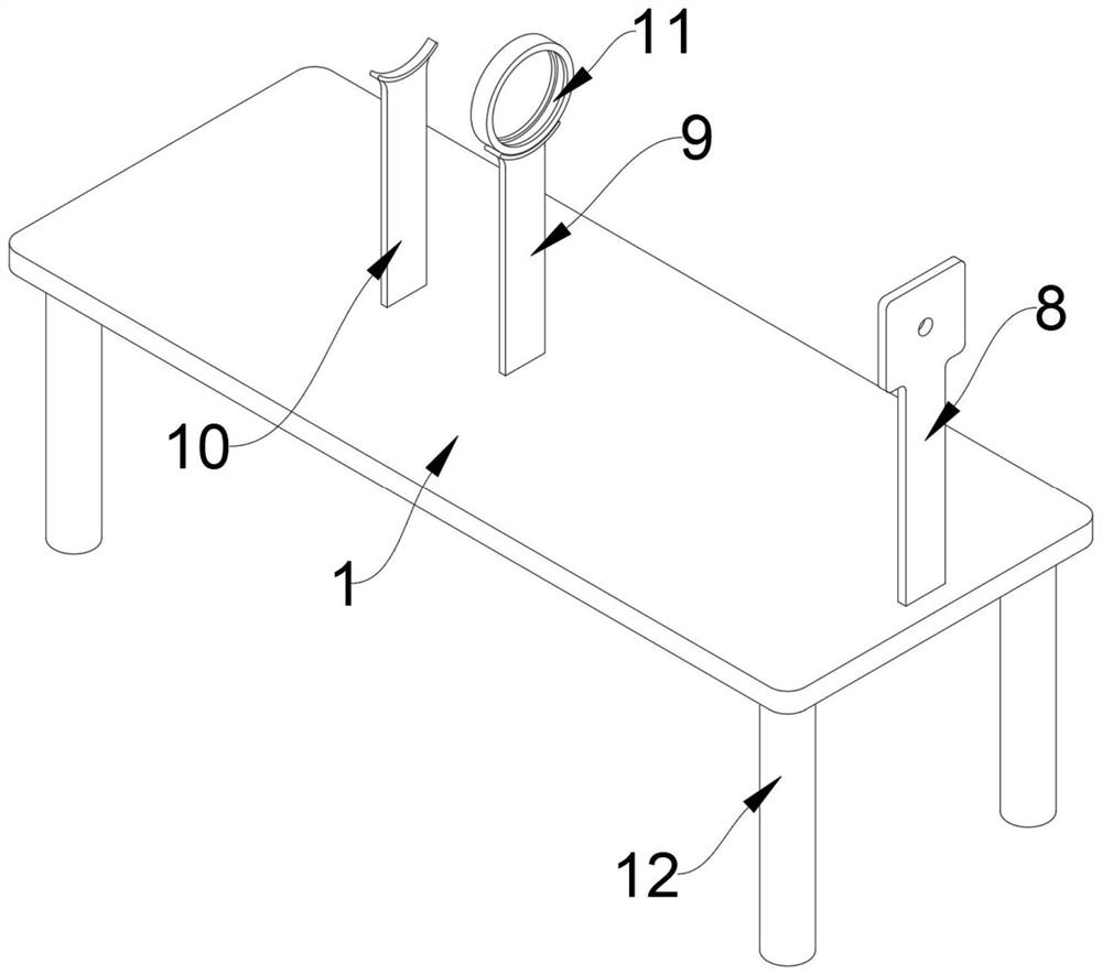
[0045] refer to Figure 1-9 , a twisting device with uniform twisting, comprising a device main body 1, one end of the upper end of the device main body 1 is welded with a storage rack 7, the storage rack 7 includes a fixed frame 701, a circular positioning ring 702 and a rotating rod 703, fixed The middle position of the frame 701 is welded to be connected with two circular positioning rings 702, and both sides of the circular positioning rings 702 are rotatably connected with a rotating rod 703, and the lower end of the device main body 1 is connected with four load-bearing rods 12 by welding, so that the device main body 1 is fixed more firmly, and the lower ends of the four load-bearing rods 12 are all socketed and connected with feet 14, so that the feet 14 can protect the load-bearing rods 12, and one end of the upper end of the device main body 1 is welded and connected with the first support plate 8, and the device body 1 The middle position of the upper end is welded ...

Embodiment 2

[0052] On the basis of the first embodiment, a method for using a twisting device with uniform twisting is disclosed, the steps are:

[0053] Step 1: Fix the four spindles for winding the yarn on the outer sides of the four rotating rods 703 respectively;

[0054] Step 2: pass one end of the yarn wound on the outer side of the spindle through the working chamber 502 and the heating chamber 603, and then pass through the threading coil 405 and wind it around the winding coil 13;

[0055] Step 3: Rotate the worm 508, drive the carriage 503 to slide inside the working chamber 502 through the worm gear 507, so that the second roller 506 contacts the yarn, and the yarn is limited by the second roller 506 and the first roller 505 ;

[0056] Step 4: start the first motor 201, and drive the storage plate 202 to rotate through the first motor 201, thereby driving the twisting disc 5 to rotate, and twisting the yarn;

[0057] Step 5: Start the second motor 301. After the second motor ...


PUM


Abstract

The invention relates to the technical field of spinning equipment, and discloses a twisting device capable of uniformly twisting. The twisting device comprises a device main body, wherein one end ofthe upper end of the device main body is in welding connection to a first support plate; the middle position of the upper end of the device main body is in welding connection to a second support plate; the upper end of the second support plate is in bolt connection to a fixed ring; and the position, at one end away from the first support plate of the second support plate, at the upper end of the device main body is in welding connection to a third support plate. A twisting disc can be arranged for limiting yarns of different dimensions during twisting, and twists and uniformly takes in yarns,so that twisting can be more uniform, wear, on the yarns, of the device can be effectively reduced; a heating mechanism can be arranged for heating the yarns to clear plush on the yarns; and a limiting mechanism can be arranged for winding the yarns at the peripheral side of a winding ring, so that a phenomenon that the yarns are wound into a cluster is effectively avoided.

Description

technical field [0001] The invention relates to the technical field of spinning equipment, in particular to a twisting device with uniform twisting. Background technique [0002] If one end of the spinning is held and the other end is turned around, the yarn can be formed. This process is called twisting. Twisting is the process of fixing the longitudinal connection between fibers. The sliver is twisted around its own axis, which is called adding a "twist". Twisting uses the bending and twisting of fibers. Bending can cause winding, and twisting can form twists. Back, but the existing device cannot limit the position when twisting yarns of different sizes, and the twisting is not uniform enough, and it is easy to cause wear on the yarn, and it cannot correct the wool on the yarn. Clean up the velvet, and it is easy to wind into a thread ball when winding the thread. Contents of the invention [0003] The purpose of the present invention is to provide a twisting device wi...

Claims


Application Information

Patent Timeline
IPC IPC(8): D01H7/02D01H13/30
CPCD01H7/02D01H13/30
Inventor 李瑞贤李应芳
Owner 宿迁市正益纺织有限公司
Why Eureka
Try Eureka