Supercharge Your Innovation With Domain-Expert AI Agents!

A compacting device for road construction

A tamping device and road construction technology, which is applied in the direction of roads, roads, road repairs, etc., can solve problems such as weak adaptability, inability to adjust the tamping strength, and inability to meet the needs of road construction, so as to achieve the effect of improving adaptability and improving tamping efficiency

Active Publication Date: 2022-02-15
崔化富
View PDF7 Cites 0 Cited by
  • Summary
  • Abstract
  • Description
  • Claims
  • Application Information

AI Technical Summary

Problems solved by technology

[0004] In the process of road construction, it is necessary to use the tamping device to tamp the ground. The existing tamping device cannot adjust the tamping strength, and the adaptability is weak, which cannot meet different road construction needs.

Method used


Image

  • A compacting device for road construction
  • A compacting device for road construction
  • A compacting device for road construction

Examples


Embodiment 1

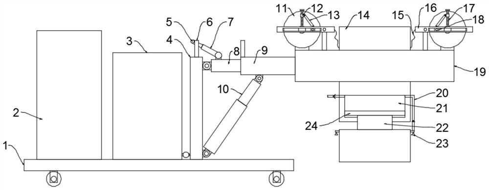
[0025] see figure 1 , in an embodiment of the present invention, a tamping device for road construction, including a tamping unit and a driving car 1 for driving the tamping unit, a counterweight 2 is installed on the end of the driving car 1 away from the tamping unit, and the tamping unit includes a tamping unit Block 14, a mounting frame 19 for installing the tamping block 14, a driving assembly for driving the tamping block 14 to move, and a mounting frame assembly for connecting the mounting frame 19 and the driving vehicle 1, and the tamping block 14 is slidably installed on the mounting frame 19 inside, on the installation frame 19, there are drive components symmetrically installed on both sides of the tamping block 14, the drive components include a first motor, a turntable 11, a drive rod 16 and an adjustment mechanism for the range of motion of the drive rod 16, and the first motor is fixed Installed on the installation frame 19, the output shaft of the first motor ...

Embodiment 2

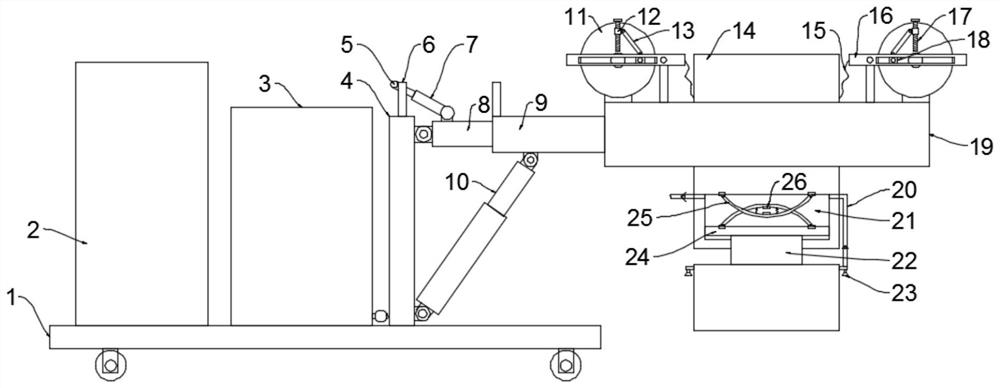
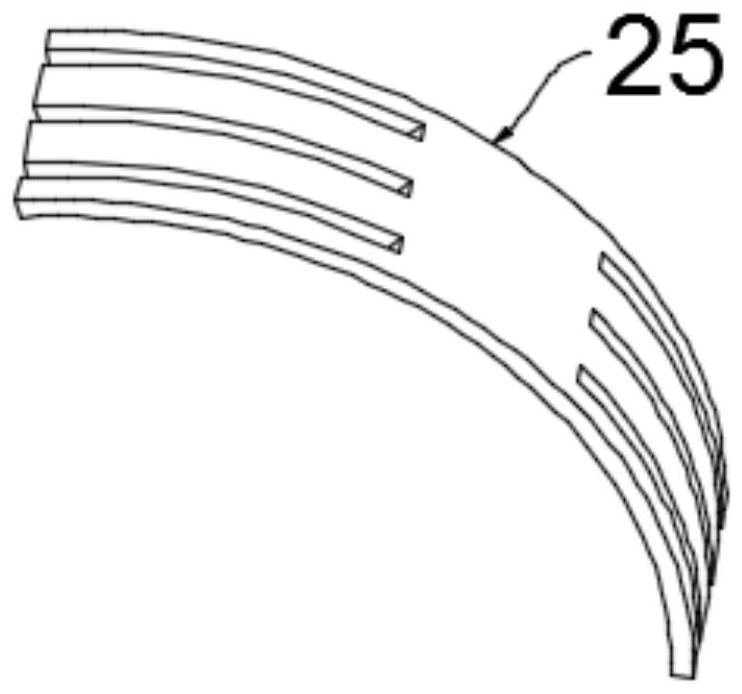
[0029] see Figure 2-3 The difference between this embodiment of the present invention and Embodiment 1 is that a buffer assembly is also provided in the chamber 21, and the buffer assembly includes an elastic member 25 and a magnet 26, and the two elastic members 25 are arc-shaped and symmetrical Setting, two elastic parts 25 are slidably installed on the piston plate 24 and the top wall of the chamber 21 respectively, the two ends of the two elastic parts 25 are rake-shaped and intersected and misplaced, and the middle parts of the two elastic parts 25 are respectively fixed with magnets 26 , the opposite faces of the two magnets 26 are the same magnetic pole, and the two elastic members 25 are also fixedly connected with springs on both sides of the two magnets 26, which can perform good buffering and shock absorption, and prolong the service life of the tamping block 14.

[0030] The working principle of the present invention is: when working, the first motor drives the tu...


PUM


Abstract

The invention discloses a tamping device for road construction, which relates to the technical field of road construction machinery and mainly aims to solve the problem that the existing tamping device cannot adjust the tamping strength; it includes a tamping unit and a driving vehicle for driving the tamping unit, and the driving vehicle is far away from the tamping device. A counterweight is installed at one end of the unit, and the tamping unit includes a tamping block, an installation frame for installing the tamping block, a drive assembly for driving the movement of the tamping block, and a mounting frame assembly for connecting the installation frame and the driving car. The drive assembly includes The first motor, the turntable, the drive rod and the adjustment mechanism for the range of motion of the drive rod also include a dust reduction unit, the dust reduction unit includes a nozzle and a water supply assembly, and the installation frame assembly includes a mounting column, a mounting rod, a casing and a hydraulic cylinder , is equipped with a driving component, which can adjust the tamping strength; is equipped with a dust reduction unit, which improves the tamping efficiency while reducing dust; is equipped with a mounting frame component, which can adjust the tamping range and tamping angle to improve adaptability.

Description

technical field [0001] The invention relates to the technical field of road construction machinery, in particular to a compacting device for road construction. Background technique [0002] The road accompanies human activities and promotes social progress and development. It is a symbol of historical civilization and a sign of scientific progress. [0003] The interpretation of ramming is reinforcement, and the extended meaning is to lay a solid foundation, which is mostly used in the construction industry. Use heavy objects to make it fall freely repeatedly, and tamp the foundation or filling soil and stone to improve its compactness. [0004] During the road construction process, it is necessary to use a compacting device to compact the ground. The existing compacting device cannot adjust the compacting strength, has poor adaptability, and cannot meet different road construction needs. Contents of the invention [0005] The object of the present invention is to provid...

Claims


Application Information

Patent Timeline
Patent Type & Authority Patents(China)
IPC IPC(8): E01C19/34E01H3/02
CPCE01C19/34E01H3/02
Inventor 崔化富池莉丹
Owner 崔化富
Features
  • R&D
  • Intellectual Property
  • Life Sciences
  • Materials
  • Tech Scout
  • Unparalleled Data Quality
  • Higher Quality Content
  • 60% Fewer Hallucinations
Learn More