Door type emergency leakage stopping device and method for underground diaphragm wall

An underground diaphragm wall and door-type technology, which is applied in excavation, underwater structures, water conservancy projects, etc., can solve problems such as threats to the safety of foundation pits and surrounding buildings, long time-consuming plugging, and loose joints in groove sections, etc., to achieve economical The benefits and social benefits are good, the plugging effect is quick, and the effect of not polluting the environment

Inactive Publication Date: 2020-10-16
NO 2 CONSTR GRP CO LTD OF SHANGHAI CONSTR GRP
View PDF5 Cites 0 Cited by
  • Summary
  • Abstract
  • Description
  • Claims
  • Application Information

AI Technical Summary

Problems solved by technology

However, underground diaphragm walls are sometimes easily affected by geological conditions, resulting in problems such as uneven concrete pouring and uneven joints of groove sections, which can easily cause leakage of underground diaphragm walls, threatening the safety of foundation pits and surrounding buildings
The leaking position of the underground diaphragm wall often has phenomena such as high gushing water pressure and mixed sediment, which cause certain difficulties for sealing
[0003] The existing plugging method is backfill plugging, which has the problems of long plugging time and difficult to guarantee the effect

Method used


Image

  • Door type emergency leakage stopping device and method for underground diaphragm wall
  • Door type emergency leakage stopping device and method for underground diaphragm wall
  • Door type emergency leakage stopping device and method for underground diaphragm wall

Examples


Embodiment 1

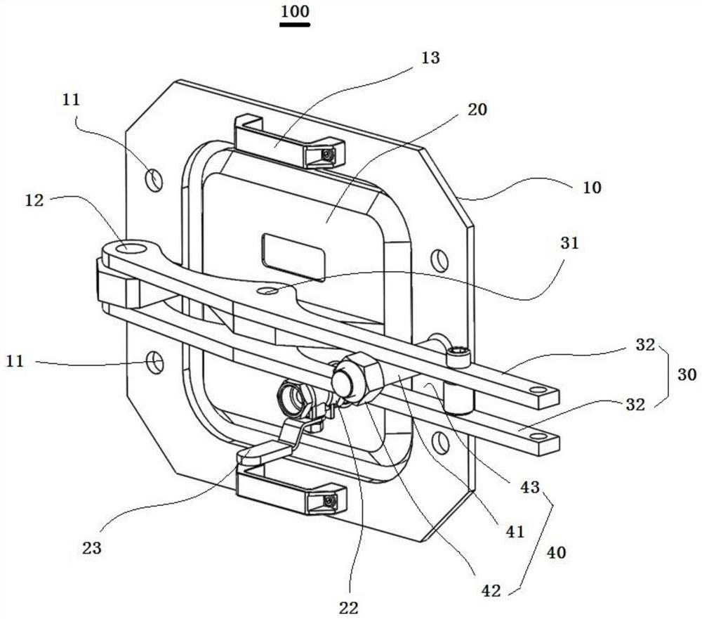
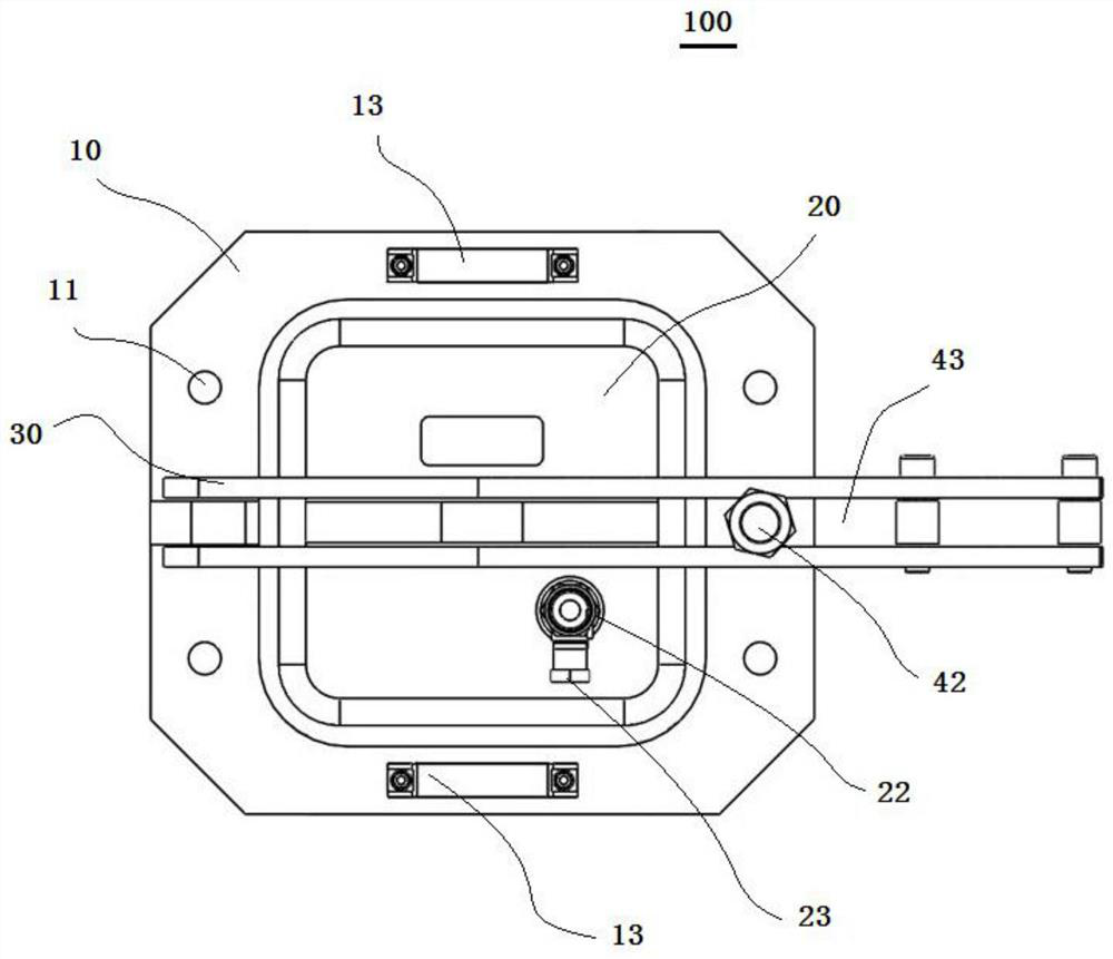
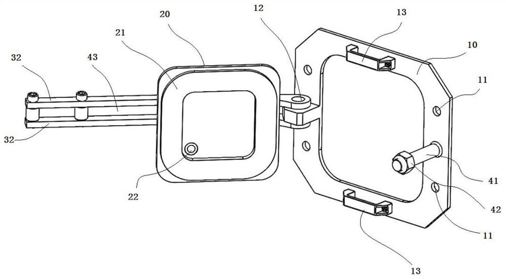
[0044] Such as Figure 1 to Figure 4 As shown, the present embodiment provides a door-type emergency leak plugging device 100 for an underground diaphragm wall, which is used for installation at the seepage of the underground diaphragm wall. The door-type emergency plugging device 100 includes: a frame 10 , a plugging door 20 , a pressing handle 30 and a safety structure 40 . The frame 10 is used to be installed at the leakage location of the underground continuous wall. The frame 10 has an anchor bolt hole 11 passing through the upper surface and the lower surface thereof, and is used to pass an expansion anchor bolt to install the door-type emergency leakage plugging device 100 at the leakage place of the underground continuous wall. The pressing handle 30 protrudes from one end of the frame 10 to the opposite end of the frame 10 . One end of the pressing handle 30 is movably connected to one end of the frame 10 through the first connecting member 12 , so that the other en...

Embodiment 2

[0058] see Figure 1-Figure 4 , the present invention also provides an emergency plugging method for an underground diaphragm wall, which uses the above-mentioned door-type emergency plugging device for plugging, and the method includes the following steps:

[0059] Step 100, find the leakage location of the underground diaphragm wall, clean and polish the surface of the underground diaphragm wall around the leakage location, and remove the floating mud and easily falling cement soil on the surface of the underground diaphragm wall;

[0060] Step 200, according to the size of the hole at the seepage of the underground diaphragm wall, select a suitable size of the door-type emergency plugging device, and drive expansion anchor bolts into the underground diaphragm wall according to the position of the anchor bolt hole 11;

[0061] Step 300, install the door-type emergency plugging device and tighten the bolts, so that the rubber ring 21 is close to the surface of the underground...


PUM


Abstract

The invention discloses a door type emergency leakage stopping device and method for an underground diaphragm wall, and belongs to the field of construction of building foundation pits. The door typeemergency leakage stopping device comprises a frame, a leakage stopping door, a pressing handle and a safety structure. The door type emergency leakage stopping device is installed at the leakage position of the underground diaphragm wall through expansion anchor bolts, the leakage stopping door is closed and sealed through grouting, and the effect of rapidly stopping leakage of the underground diaphragm wall is achieved. The door type emergency leakage stopping device and method have the advantages that the device is simple and convenient to mount, large machines do not need to be operated ina foundation pit, the leakage stopping effect is rapid, the device is not affected by water pressure, the environment is not polluted, and economic benefits and social benefits are good.

Description

technical field [0001] The invention relates to an underground diaphragm wall door-type emergency leak plugging device and method, and belongs to the construction field of building foundation pit construction. Background technique [0002] As a common foundation pit enclosure structure, the underground diaphragm wall's compact waterproof performance directly affects the safety of the foundation pit. However, underground diaphragm walls are sometimes easily affected by geological conditions, resulting in problems such as uneven concrete pouring and uneven joints of groove sections, which can easily cause leakage of underground diaphragm walls, threatening the safety of foundation pits and surrounding buildings. In the leakage position of the underground diaphragm wall, there are often phenomena such as high gushing water pressure and mixed sediment, which cause certain difficulties in sealing. [0003] The existing plugging method is backfill plugging, which has the problems...

Claims


Application Information

Patent Timeline
IPC IPC(8): E02D17/04E02D29/16
CPCE02D17/04E02D29/16
Inventor 龙莉波施陈裴如俊王竹君
Owner NO 2 CONSTR GRP CO LTD OF SHANGHAI CONSTR GRP
Why Eureka
Try Eureka