Scour monitoring system and method for buried pipeline

A monitoring system and pipeline technology, applied in pipeline systems, measuring devices, instruments, etc., can solve the problems of poor monitoring effect, long interval time, and difficulty in covering the entire pipeline along the pipeline, and achieve the effect of improving the monitoring effect.

Inactive Publication Date: 2020-10-16
盛碧云
View PDF5 Cites 1 Cited by
  • Summary
  • Abstract
  • Description
  • Claims
  • Application Information

AI Technical Summary

Problems solved by technology

[0005] However, there are deficiencies in finding water-damaged locations through manual inspection: because the transmission pipelines are often very long, especially for natural gas, oil and other transmission pipelines, most of them are located in areas that are difficult for people to reach, even underwater, so the frequency of inspections is average. It is relatively low, and the interval time is relatively long. It is possible that the overlying soil layer of a certain pipeline has been washed away, and the pipeline was exposed for a long time or was discovered by the inspection personnel after the pipeline crossed the river and floated up.
[0006] However, due to cost reasons, the video surveillance solution is difficult to fully cover the pipeline. Video surveillance equipment can only be installed at key locations, and it is impossible to monitor the underwater soil erosion of the pipeline crossing the river, resulting in poor monitoring effect.
[0007] However, the use of satellite remote sensing or UAV solutions is affected by timeliness. It usually takes several days for satellites to cover the target area again, and is easily affected by surface vegetation.
UAVs need manual control, and the working radius and battery life are also difficult to meet the real-time monitoring of long pipelines
[0008] The cost of the optical fiber sensing monitoring solution along the way is relatively high, and the monitoring equipment needs to be arranged on the pipeline during the pipeline construction, otherwise it needs to be excavated again, and the cost is too high
[0009] Therefore, it is urgent to solve the problem of poor soil scour monitoring for long-term buried pipelines.

Method used


Image

  • Scour monitoring system and method for buried pipeline
  • Scour monitoring system and method for buried pipeline
  • Scour monitoring system and method for buried pipeline

Examples


Embodiment 1

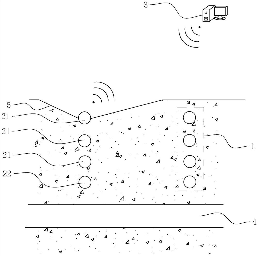
[0050] refer to figure 1 , the system includes multiple sets of monitoring components 1 and a server 3 communicating with the monitoring components 1; multiple sets of monitoring components 1 are buried in the soil layer 5 and located above the pipeline 4, and multiple sets of monitoring components 1 are along the length direction of the pipeline 4 Arranged in sequence. It should be noted that multiple sets of monitoring components 1 do not need to be located directly above the pipeline 4, and sometimes the impact of construction on the pipeline 4 is worried, so the monitoring components 1 need to be properly deviated and placed on one or both sides of the pipeline 4; Or in order to detect problems earlier, the monitoring component 1 can be arranged on the side of the direction where the water flows.

[0051] The monitoring assembly 1 includes a monitoring part 21 and an early warning part 22. The monitoring parts 21 are arranged in multiples and arranged in sequence along th...

Embodiment 2

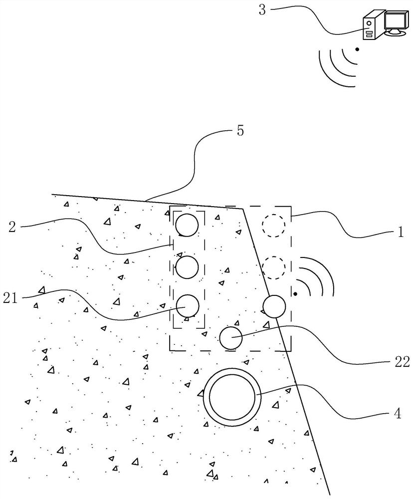
[0062] refer to image 3 , the difference between this embodiment and Embodiment 1 is that each group of monitoring components 1 includes at least two columns of monitoring element groups 2, and this embodiment takes two columns of monitoring element groups as an example, and each column of monitoring element groups 2 includes a plurality of edge For the monitoring elements 21 arranged in the vertical direction, the connection direction of the two rows of monitoring element groups 2 is perpendicular to the extension direction of the pipeline 4 , and the two rows of monitoring element groups 2 are located above the two sides of the pipeline 4 .

[0063] The implementation principle of embodiment 2 is: when the system is applied to the monitoring of slope water damage, the water flow erosion may cause the slope to collapse, forming a nearly 90-degree fracture surface. In this case, the system in embodiment 1 is due to The monitoring part 21 and the early warning part 22 are loca...

Embodiment 3

[0065] refer to Figure 4 The difference between this embodiment and Embodiment 1 is that an early warning accessory 27 is provided between two adjacent groups of monitoring components 1 , and the early warning accessory 27 is also located above the pipeline 4 . The structure of the early warning accessory 27 is the same as that of the early warning accessory 22 , and the embedding distance between the early warning accessory 27 and the pipeline 4 is also equal to the embedding distance between the early warning accessory 22 and the pipeline 4 .

[0066] The implementation principle of Embodiment 3 is as follows: the purpose of setting up the early warning accessory 27 is to increase the early warning range along the length direction of the pipeline 4 and help the staff to know the surrounding conditions of the pipeline 4 more timely and comprehensively.


PUM


Abstract

The invention relates to a scour monitoring system and method for a buried pipeline, and relates to the field of pipeline safety monitoring, and the scour monitoring system comprises at least one group of monitoring assemblies and a server; the monitoring assembly comprises an early warning piece buried in a soil layer and located above the pipeline, and the distance between the early warning piece and the pipeline is h1; the early warning piece is used for sending early warning information after the upper surface of the soil layer descends to the early warning piece due to water flow scouringand other reasons, and the early warning information mainly comprises serial number data of the early warning piece; and the server is used for receiving the early warning information and generatingan early warning event according to the early warning information, wherein the early warning event comprises recording the number data of the early warning piece and the receiving time of the early warning information. And finally, the worker can know the soil layer scouring position and time according to the received number data of the early warning piece and the receiving time. According to theinvention, the scour monitoring effect of the long-line-segment buried pipeline is improved.

Description

technical field [0001] The present application relates to the field of pipeline safety monitoring, in particular to a flushing monitoring system and method for buried pipelines. Background technique [0002] Pipelines are indispensable material transportation facilities for important systems such as natural gas, oil, urban heating, water supply, and gas, and are of great significance to the development of the national economy and the transportation of energy and materials. At the same time, the investment in pipeline facilities is huge, and most of them are installed in pipeline trenches or buried below the ground. They have a certain degree of concealment in space. Pipelines exposed outside the soil layer may be damaged by a third party or corroded by the air, and it is difficult to find them in time because pipeline projects generally have long lines and are mostly located in sparsely populated areas. [0003] Among them, soil erosion is a special disaster that is ubiquit...

Claims


Application Information

Patent Timeline
Patent Type & Authority Applications(China)
IPC IPC(8): G01D21/00F17D5/00
CPCF17D5/00G01D21/00
Inventor 盛碧云林颖典
Owner 盛碧云
Why Eureka
Try Eureka