
Electronic analytical balance for mass measurement

An electronic analytical balance and mass measurement technology, which is applied to weighing equipment, weighing, and measuring devices using electromagnetic balance, can solve the problem of reduced accuracy of the quality measurement results of liquid medicines, low weighing efficiency of liquid reagents, and liquid reagents. Weighing steps increase and other problems, to achieve the effect of improving weighing and measuring accuracy, improving weighing efficiency, and reducing weighing steps

Active Publication Date: 2020-10-16
安徽圣仁电子科技有限公司
View PDF10 Cites 0 Cited by
  • Summary
  • Abstract
  • Description
  • Claims
  • Application Information

AI Technical Summary

Problems solved by technology

[0004] Yet, because in the laboratory, chemical reagent has two kinds of states of solid and liquid, and existing electronic analytical balance is when weighing liquid reagent, because can't carry out chemical reaction before and after the round bottom flask and test tube that fill liquid reagent directly. Overall mass measurement, therefore, it is necessary to transfer the reagents in the round bottom flask or test tube to the flat bottom beaker, place the flat bottom beaker on the tray for mass measurement, and then transfer to the round bottom flask or test tube for mass measurement before and after chemical reaction, Increases the weighing steps of liquid reagents, resulting in inefficient weighing of liquid reagents, and losses during transfer of liquid reagents, which in turn leads to a decrease in the accuracy of liquid reagent quality determination results

Method used


Image

  • Electronic analytical balance for mass measurement
  • Electronic analytical balance for mass measurement
  • Electronic analytical balance for mass measurement

Examples


Embodiment Construction

[0025] The following will clearly and completely describe the technical solutions in the embodiments of the present invention with reference to the accompanying drawings in the embodiments of the present invention. Obviously, the described embodiments are only some, not all, embodiments of the present invention. Based on the embodiments of the present invention, all other embodiments obtained by persons of ordinary skill in the art without making creative efforts belong to the protection scope of the present invention.

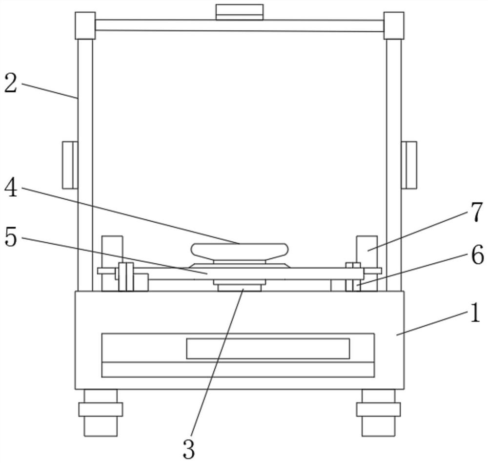
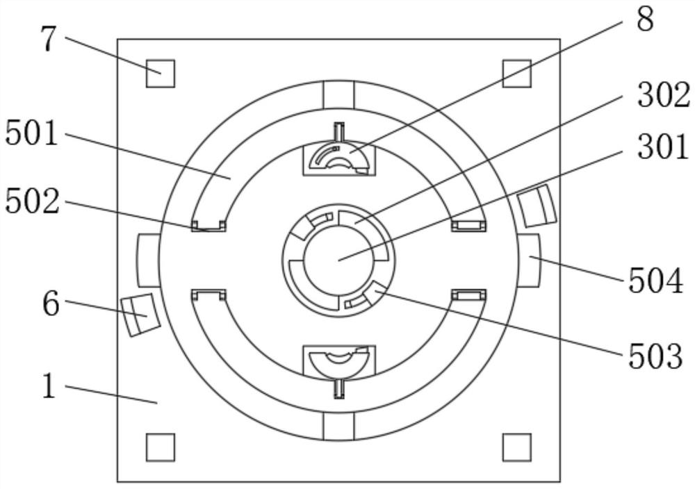
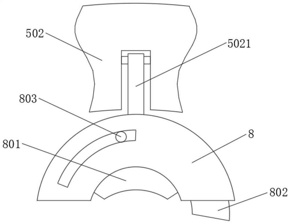
[0026] see Figure 1-8, an electronic analytical balance for mass determination, comprising an electronic analytical balance seat 1, the four corners of the top of the electronic analytical balance seat 1 are fixedly connected with support rods 2, and glass doors are arranged between any two of the four support rods 2, and the glass doors The number of doors is four, and the four glass doors are respectively located on the two sides, the front, and the top of ...


PUM


Abstract

The invention relates to the field of electronic weighing equipment. The invention further discloses an electronic analytical balance for mass measurement. The electronic analytical balance for mass measurement comprises an electronic analytical balance seat; five sealed glass doors are arranged at the top of the electronic analytical balance seat; a weighing linkage shaft for weighing transmission is arranged in the middle of the top end of the electronic analytical balance seat; the top of the weighing linkage shaft is fixedly connected with a tray located above the electronic analytical balance seat; and the bottom end of the weighing linkage shaft is connected with a weighing metering mechanism in the electronic analytical balance seat. The invention discloses an electronic analyticalbalance for mass measurement. An auxiliary supporting ring structure additionally linked with the tray is additionally arranged; by utilizing the semi-ring clamping plates on the two sides of the auxiliary supporting ring, a round-bottom flask or a test tube containing a liquid reagent can be conveniently clamped for mass measurement, the round-bottom flask and the liquid reagent do not need to betransferred to a beaker, and then the beaker is placed on a tray for mass measurement, so that the weighing steps of the liquid reagent are reduced, and the weighing efficiency of the liquid reagentis improved.

Description

technical field [0001] The invention relates to the field of electronic weighing equipment, in particular to an electronic analytical balance for mass measurement. Background technique [0002] The electronic analytical balance is a kind of electronic balance with high precision in mass determination. Its determination is accurate to 0.1 mg. At the same time, it uses the sensor technology, analog technology, digital electronic technology and microprocessor technology of the electronic balance. Automatic display, tare weight removal, automatic data output, automatic fault tracing, overload protection and other functions, electronic balances usually use electromagnetic force sensors (see load cells) to form a closed-loop automatic adjustment system with high accuracy and stability Well, due to the high measurement accuracy of the electronic analytical balance, it is commonly used for accurate weighing of laboratory reagents to understand the changes of each test product before...

Claims


Application Information

Patent Timeline
IPC IPC(8): G01G7/02G01G17/00G01G17/04G01G21/02G01G21/22G01G21/28G01G23/00
CPCG01G7/02G01G17/00G01G17/04G01G21/02G01G21/22G01G21/28G01G23/00
Inventor 付贤安
Owner 安徽圣仁电子科技有限公司
Learn More